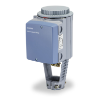
SKP70…U.. Air/Gas Ratio Controlling Actuators Technical Instructions
155-516P25
Rev. 2, December, 1998
Siemens Building Technologies, Inc P
PP
Pa
aa
age
ge ge
ge 3
33
3
o
oo
of
f f
f 9
99
9
Landis Division
S
SS
Sp
pp
pe
ee
ec
cc
ci
ii
if
ff
fi
ii
ic
cc
ca
aa
at
tt
ti
ii
io
oo
on
nn
ns
ss
s
Agency approvals
As safety shut-off valve UL/429, FM/7400, CGA/3.9,
AGA/Z 21.21 in combination with
VG…U.. series gas valves
UL recognized when used with other valves.
Power supply
Operating voltage 110 to 120 Vac + 10%-15%
220 to 240 Vac + 10%-15%
Operating frequency 50 to 60 Hz + 6%
Power consumption 20 VA
Duty cycle 100%
Operating environment
Ambient operating temperature 15
o
to 140
o
F (-10
o
to 60
o
C)
Mounting position Optional, with diaphragms in vertical
position but not upside down
Maximum temperature of air and flue
gas at the control connections 140
o
F (60
o
C)
Maximum inlet gas pressure Same as VG… valve
Physical characteristics
Weight 5.5 lb (2.5 kg)
Enclosure NEMA 1, 2, 5 and 12 for indoor use
Dimensions
See
Figure 6
Specification for valves
See
gas valve Technical Instruction
No. 155-512P25
Connections
Conduit connection ½-inch NPSM adapter
Gas/air/combustion chamber pressure
connections ¼” NPT
Operating characteristics
Output force 100 lb (450 N)
Maximum stroke 0.7” (18 mm)
Opening time for maximum stroke 12 s
Closing time < 0.8 s
Control signal
Reference input signal Combustion air pressure
Control characteristic integral action
Operation/installation
Setting range of gas to air pressure ratio 0.4:1 to 9:1
Permissible pressures
during operation for accurate control Min. air presssure: 0.2” w.c.
Max. air pressure: with Pg/Pa <2; 20” w.c.
Max. air pressure: with Pg/Pa >2; 12” w.c.
with higher air pressures use AGA78
Min. downstream gas pressure: 0.4” w.c.
Max. downstream gas pressure: 40” w.c.
Minimum time required for high to low
fire load changes Approx. 5 s
Permissible leakage test pressure 20 psi
Permissible leakage test vacuum 3 psi
Minimum diameter of impulse pipes ¼” inside diameter (
See
Installation)
Minimum distance between gas
impulse pipe connection and gas
valve outlet 5 x pipe diameter
Auxiliary features
Capacity of auxiliary switch 6 (3) A, 250 Vac
Setting range of auxiliary switch Full stroke
 Loading...