SKP70…U.. Air/Gas Ratio Controlling Actuators Technical Instructions
155-516P25
Rev. 2, December, 1998
Siemens Building Technologies, Inc P
PP
Pa
aa
age
ge ge
ge 7
77
7
o
oo
of
f f
f 9
99
9
Landis Division
St
StSt
Sta
aa
ar
rr
rt
t t
t up
upup
up
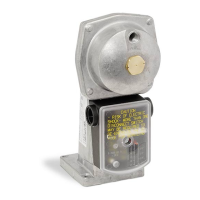
Regulator (
See
Figures 2
and 3)
The pressure ratio and bias adjustment screws are located on top of the regulator under
a sealable cover plate. The actual settings can be seen through windows on each side of
the regulator.
N
NN
No
oo
ot
tt
te
ee
e:
::
: The burner capacity is controlled by the position of the air damper. The
combustion quality (air/gas ratio) is controlled by the settings on the regulator (the
+ and – indications relate to the change in gas flow). Adjustment in clockwise
direction decreases the gas flow.
1.
Set the gas to air ratio to the desired value using the adjusting screw
•
(coarse
setting).
2.
Start the burner and run it at approximately 90% of full capacity.
3.
Measure CO
2
or O
2
content in the flue gases and correct the ratio by adjusting screw
•
until optimum values are obtained (fine setting).
4.
Return to low fire and measure the CO
2
or O
2
content in the flue gases. If necessary,
correct the setting by adjusting screw
•
until optimum values are obtained.
5.
Limit the damper position for low fire operation. If considerable parallel displacement
was necessary to achieve optimum combustion, repeat the procedure from step 3.
6.
Run the burner to the required high fire position and limit the air damper position.
7.
Check the flue gas values at several intermediate output levels. If corrections are
necessary, note the following:
x
Adjust the pressure ratio screw
•
at high fire operation only.
x
Adjust the bias screw
•
at low fire operation only.
If the air pressure exceeds the maximum value of 12” or 20” w.c. (
See
Specifications), the pressure must be reduced by means of a pressure reducing
T-fitting (AGA78).
F
FF
Fi
ii
ig
gg
gu
uu
ur
rr
re
e e
e 3
33
3.
. .
. A
AA
Ad
dd
dj
jj
ju
uu
us
ss
st
tt
tm
mm
me
ee
en
nn
nt
tt
ts
ss
s.
..
.
 Loading...