)
SKP25U.. Pressure Regulating Gas Valve Actuators Technical Instructions
Document Number 155-752
July 9, 2014
Siemens Building Technologies, Inc. Page 3
Specifications,
Continued
Physical characteristics
Weight 3.5 lb (1.6 kg)
Enclosure NEMA 1, 2, 5 and 12 for indoor use
NEMA 3, 3R, and 4 with optional AGA66 gasket
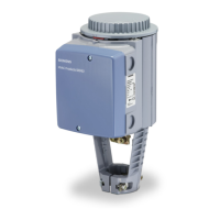
Dimensions See Figure 3
Specification for valve bodies See gas valve Technical Instructions,
P/N 155-512P25
Connections Conduit connection Two 1/2-inch NPSM threaded knock-outs
Electrical connection Spring loaded terminals for 14 AWG wires
Gas connection 1/4” NPT
Air connection 1/4” NPT
Gas pressure test connection Hose barb with close-off screw
Operating characteristics Output force 100 lb (450 N)
Maximum stroke 1 inch (26 mm)
Opening time for maximum stroke Varies with valve size, 14 seconds for max. stroke
Closing time < 0.8 seconds
Operation/installation Outlet pressure spring range 0" to 8.5" WC ( standard, unpainted spring, AGA29)
for SKP25.0 models 6" to 48" WC (yellow spring, AGA22)
40" to 100" WC (red spring, AGA23)
for SKP25.411U1 models 1.5 to 10 psi (standard, yellow spring, AGA22)
8.5 to 20 psi (red spring, AGA23)
With air pressure loading for SKP25.4 ± 0.6" WC bias (black spring AGA28)
models or zero governor
or for SKP25.611U1 0" to – 4" WC bias (white spring)
Maximum sensing line pressure 20 psi
Maximum sensing line vacuum 3 psi for SKP25.0 models
Minimum sensing line diameter 1/4" inside diameter
Minimum distance between
sensing line and gas valve outlet 5 times the pipe diameter
Minimum time required for high to low fire 5 seconds
load changes
Auxiliary features Proof of closure switch Non-adjustable
Setting range of auxiliary switch 40% to 100% of stroke
Switch rating 6A/250 Vac resistive; 3A/120 Vac pilot duty
 Loading...