EasyManua.ls Logo

Siemens SQM50 series User Manual

Siemens SQM50 series
6 pages
To Next Page IconTo Next Page
Page #1 background imageLoading...
Page #1 background image
Installation Instructions
Document No. 129-401
January 18, 2008
SQM5… Reversing Actuators, with Multiple Analog Control Input
Signals
Item Number 129-401, Rev. DA Page 1 of 6
Product Description
Reversing actuator used to position flow control
valves, butterfly valves, dampers, or any application
requiring rotary motion with multiple analog input
signals.
Product Numbers
SQM5x.xxxRxZx for 4 to 20 mA, 0 to 135 ohm and
0 to 10 Vdc input signals
Actuator Torque:
SQM50.2… 90 in/lb
SQM50.3… 90 in/lb
SQM50.4… 140 in/lb
SQM53.4… 200 in/lb
SQM56.5… 310 in/lb
SQM56.6… 400 in/lb
Max Shaft Torque:
AGA58.1 200 in/lb
AGA58.3 220 in/lb
AGA58.4 270 in/lb
AGA58.7 400 in/lb
SQM… motors allow torque on either end of the
AGA58.3 and AGA58.4 shafts.
NOTE: For detailed information, see Technical
Instructions (155-517P25).
Caution Notations
CAUTION:
Equipment damage may occur
if you do not follow the
procedures as specified.
Installation
Cover Removal
Use a Phillips screwdriver to loosen the two screws
on the actuator cover corners. See Figure 1.
Lift the screws and raise the cover. See Figure 2.
EA0564R1
EA0568R1
Figure 1. Figure 2.
Rotational Direction Verification
Actuator model numbers that end with “R” are
factory configured for clockwise (cw), minimum to
maximum rotation when facing the gear end of the
actuator, or counterclockwise (ccw) rotation when
facing the other end of the actuator. The gear end of
the actuator is the side opposite of the visual
position indicator.
Actuator Mounting
SQM5… actuators can be mounted in any
orientation. Optional base mounting brackets are
available.
SQM5… actuators can also be face mounted using
self-tapping screws in combination with the various
holes on the face of the actuator gear end.
Switch Adjustment
SQM5…actuators are factory-wired with Switch I
(maximum), Switch II (fully closed/economy position)
and Switch III (minimum/low-fire). The individual
switch cams I, II, and III are factory set to 90°, 0°
and 10°, respectively. See Figures 3 and 4.
Question and Answer IconNeed help?

Do you have a question about the Siemens SQM50 series and is the answer not in the manual?

Siemens SQM50 series Specifications

General IconGeneral
BrandSiemens
ModelSQM50 series
CategoryController
LanguageEnglish

Summary

Product Overview and Safety

Product Description

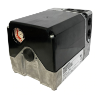
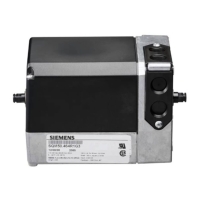
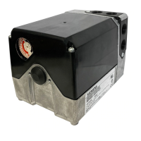
Details the purpose and application of the reversing actuator.

Product Numbers

Lists actuator models and their torque specifications.

Caution Notations

Highlights potential equipment damage if procedures are not followed.

Initial Installation and Setup

Cover Removal

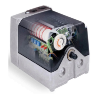
Instructions for removing the actuator cover using a Phillips screwdriver.

Rotational Direction Verification

Explains how to verify clockwise or counterclockwise rotation based on model.

Actuator Mounting

Describes mounting orientations and optional brackets for SQM5 actuators.

Switch Adjustment

Details factory settings and adjustment of internal switches.

Actuator Calibration and Adjustment

Shaft Adjustment

Procedure to disengage and manually rotate the actuator shaft.

Cam Drum Adjustment

Steps to align the cam drum to the zero position.

Position Indicating Dial Adjustment

Ensuring the position indicator dial aligns with the scale.

Electrical Connection and Grounding

Electrical Connection

Details conduit connections and power supply requirements for SQM5 actuators.

Grounding

Procedure to ground the actuator to avoid electromagnetic interference.

Commissioning Procedures

Manual Operation

Steps to set up and test the actuator in manual mode.

Automatic Operation

Instructions for connecting and enabling automatic operation.

Control Adjustments

Modulation Adjustment

Adjusting trim potentiometers for minimum and maximum positions.

Zero Adjustment

Setting the minimum position using the MIN trim potentiometer.

Span Adjustment

Adjusting the maximum position using the MAX trim potentiometer.

Advanced Functions

Electronic Linearization Function

Enabling linearization to improve flow curve characteristics.

Input Signal Override

Using line voltage to drive actuator to a preset position.

Parallel Operation

Configuring the actuator for parallel operation with jumper J2.

Master/Slave Operation

Configuring the actuator for master/slave operation with jumper J2.

Split Ranging

Utilizing signal shift for split ranging functionality.

Final Installation and Dimensions

Dimensions

Provides SQM5 actuator dimensions in inches and millimeters.

Cover Installation

Steps to install the actuator cover after setup.

Related product manuals