Document No. 129-401
Installation Instructions
January 18, 2008
Electrical Connection
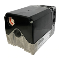
SQM5… actuators are equipped with two removable
conduit connection plates located on the upper
corner of the gear housing. Each plate is provided
with two threaded connections for 1/2-inch NPSM
conduit connectors. The use of flexible stranded wire
is recommended.
NOTE: SQM5… Actuators require a single-source,
single-phase power supply.
Grounding
To avoid electro-magnetic interference, SQM5…
actuators must be grounded. The ground screw is
located to the right of the AUTO/MAN switch (below
the shaft release button).
CAUTION:
Disconnect circuit board wire marked 51
during high voltage testing. Reconnect it to
the grounding terminal after the test.
EA0557R6
AGA56.9...
Y
0...3
25% 50%
75%
MAX
MIN
0 or 12 mA
10 mA
8 mA
6 mA
14 mA
16 mA
18 mA
25%
50%
75%
MAX
4 mA
20 mA
MIN
ZF =
POS
POS
LIN
Y
0...3
Y
0...3
POS
2
1
J1
J2
2
REG
MAX
MIN
Y
0...3
MIN MAX
OPE
MAX
MIN
MAX
MIN
SHIFT
LIN
1
(+2 V)
135 Ohm
4...20 mA
0...10 V
0...20 mA
4...20 mA
0...10 V
0...20 mA
4...20 mA
123
11 21
M
I
II
III
IV V
12 22 13 23
14
15
24 25
45
1 2 13 3
21 12
51
N
VI
16
26
6
wire leads
A
L
Z
ZL
L
1N
P
ZF
M
U3
M
U4
M
Y
0
M
Y
3
M
Y
1
M
Y2
U2
U1
"Economy"/Fully closed
Minimum/Low fire
Maximum/High fire
Auxilliary
IV...VI
III
II
I
actuator switch
common
0...2 V
R
B
W
MAN AUTO
shown in
auto position
ASZ...
(1000 Ohm)
b
a
c
for ccw
rotation
brown
black
blue
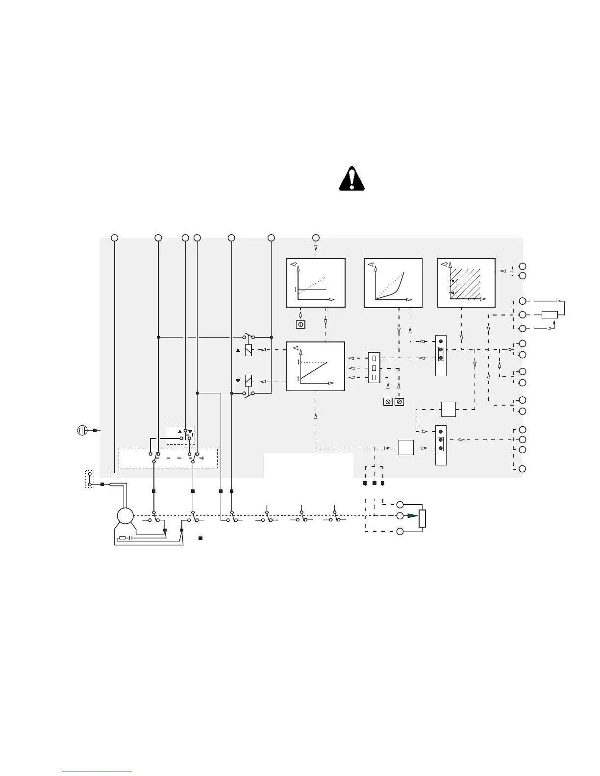
Figure 4. Basic Functional Diagram of AGA56.9…
Siemens Building Technologies, Inc.
Page 3 of 6
 Loading...