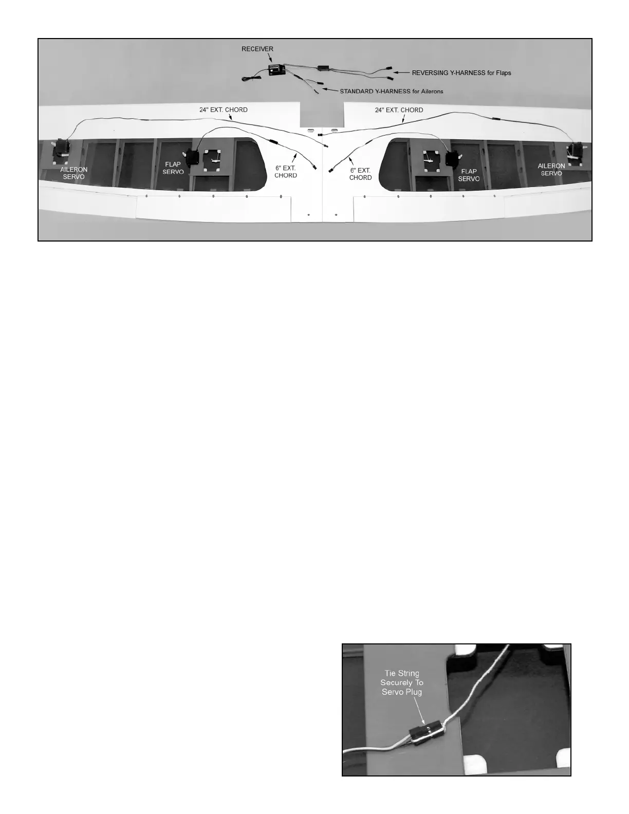
AILERON AND FLAP RADIO EQUIPMENT (see photo above)
AILERONS: Both aileron servos need a 24" extension chord in
order to exit at the center of the wing. A standard Y-harness stays
plugged into the receiver for the ailerons. When the wing is put on
the airplane, the aileron extension chords are plugged into the
Y-harness.
FLAPS: Both aileron servos need a 6" extension chord in order to
exit at the center of the wing. A reversing Y-harness stays plugged
into the receiver for the flaps. When the wing is put on the
airplane, the flap extension chords are plugged into the Y-harness.
1) Attach the appropriate length extension chords onto the end of
each aileron and flap servo wire. Wrap each connection with a
piece of plastic tape, or heat-shrink tubing, to insure that it won't
come unplugged in flight. Also prepare the servos for mounting by
installing the rubber grommets and eyelets (supplied with your
radio system) in each servo.
2) Examine the wing panels closely. Inside the aileron and flap
servo bay openings you will see a short length of wood with a
string tied to it. These strings will be used to pull the aileron and
flap servo wires through the wing panel to the center of the wing.
Also note, on the bottom of each wing panel, at the center front
location, you will see an oblong opening. This is where the aileron
and flap servo wires will exit the wing panel. Inside this opening,
you will see another piece of wood with strings tied to it - this is the
other end of the strings in the aileron and flap servo bays. Leave
all of the wood pieces and strings in place for now while we mount
the aileron and flap servos to their hatches.
3) From the kit contents locate the following items:
(4) Aileron and Flap Servo Hatches
(8) 3/8" x 3/4"sq. Hardwood Servo Mounting Blocks
(8) M2.6 x 8mm PWA Mounting Screws
Notice that all four hatches are the same outer dimensions, and
thus, share the following common steps. However also notice that
there are right and left hatch covers, made to fit the right and left
wing panel hatch openings.
4) The aileron and flap servos will be mounted to the back
uncovered sides of their respective servo hatches.
a. First, position the servo on the backside of the hatch, with its
output arm directly over the center of the hatch's clearance slot.
Hold the servo tightly in position while you mark the correct
locations for two hardwood mounting blocks. Then set the servo
aside.
b. Use epoxy or slow CA glue to mount the 3/8" x 3/4" sq.
hardwood servo mounting blocks in correct position on the hatch.
Let the glue dry before proceeding.
c. Use eight M2.6 x 8mm PWA Mounting Screws to reinforce the
mounting of the blocks to the hatch. First use a ruler to find the
center of each block and mark it on the covered side of the hatch.
Drill a 1/16" dia. pilot hole at the mark - about 1/4" deep - through
the hatch and into the mounting block. Install a M2.6 x 8 mm PWA
Screw in the hole. Repeat for all the other mounting blocks on all
the hatches.
NOTE: ALL OF THE PHOTOS ON PAGE 6 OF THE ASSEMBLY
MANUAL ARE STILL APPLICABLE.
d. Finally, mount the aileron and flap servos in position on their
mounting blocks, using the servo mounting screws provided with
your radio system. To avoid possibly splitting the mounting blocks
with the screws, it's recommended that you first pre-drill pilot holes
in the wood with an under-size drill bit.
old photo 0020.tif
5) Pulling the aileron and flap servo wires through the wing.
a. Start with one of the aileron servos. In the aileron servo bay
opening, gently break loose the wood piece with the string tied to
it. Pull it and the string a few inches out of the aileron servo bay
opening. Remove the wood from the string and discard the wood.
Tie the end of the string securely to the end of the aileron servo
plug, as shown. It's best to tie the string on behind the plug, so
that it can't slip loose. Look at the closeup photo below - we
looped the string completely around the plug (fore and aft
direction), running the string between two of the wires at the back
of the plug. Do not pull the chord through the wing panel yet!
3
 Loading...