Do you have a question about the Sigma Controls 100 Series and is the answer not in the manual?
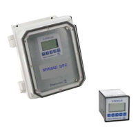
The Sigma Controls 100 series pump controllers are micro-controller based devices designed for managing the operation of 2 or 3 loads (pumps, compressors, etc.) with user-programmable alternation and/or sequencing, including process alarm(s). These instruments are designed for DIN rail mounting and provide either primary or backup control in industrial and water/wastewater applications. They feature two side-mounted push buttons for user programming and a front panel with 16 LED indicators for displaying programming prompts and process status during normal operation.
The controllers are designed for user-friendly programming and operation. Two user push buttons and front viewable LED indicators facilitate interaction.
To enter programming mode, hold "MODE and SELECT SWITCHES" until all LEDs light up. After 5 seconds, the LED test will go off, and the program LED will be on.
To enter programming mode, hold "MODE and SELECT SWITCHES" until all LEDs light up. After 5 seconds, the LED test will go off, and the program LED will be on.
Sigma Controls, Inc. products are warranted to be free from defective materials and workmanship for one (1) year from the date of shipment. The company reserves the right to repair or replace at its option any product found to be defective. In no event shall Sigma Controls, Inc. be liable for any consequential, incidental, or special damages, and the limit of its liability shall not exceed the purchase price of the supplied equipment.
Sensors and cables that have been used in wastewater or hazardous liquids must be thoroughly cleaned before returning. Units returned unclean will be considered unrepairable and returned to the sender or discarded. Do not submerge units for cleaning with cable cut or removed. This will allow cleaning fluid to enter housing, damaging electronics and voiding the warranty.
Return status can be determined upon factory inspection of returned equipment. A completed Return Authorization form must accompany all items returned for repair. Repairs will be evaluated as quickly as possible. Cost for non-warranty repairs will be provided to the customer for approval prior to any work being performed.
The form requires the user's company name and address, phone number to contact for information, reason for return, possible cause of problem, and details regarding sensor and cable installation (to ensure proper handling in case liquid has entered the sensor body). It also includes sections for urgency of repair, calibration desired for sensor or meter, PO number for non-warranty repairs, and M.S.D.S. if applicable.
Please pack in anti-static protection suitable for sensitive electronic devices.
| Brand | Sigma Controls |
|---|---|
| Model | 100 Series |
| Category | Controller |
| Language | English |