2.4 Connecting Your Signal Hound
2.4.1 SM200A/B – SM435B
With the Spike software and USB drivers installed, you are ready to connect your device. For the
USB SM devices, plug in the male USB 3.0 into your PC’s USB 3 port, and then plug the USB 3.0
Micro-B male connection into the SM device. Your PC may take a few seconds recognizing the
device and installing any last drivers. Wait for this process to complete before launching the Spike
software. For the most reliable connection, please use the included USB cable.
2.4.2 SM200C
For full setup instructions and network troubleshooting for the SM200C, see the network
configuration manual.
2.4.3 ⚠Caution – SM200 / SM435 Surfaces May Be Hot
Depending on operating conditions, ambient temperature, and air flow around the unit, the SM200
or SM435 may be hot to the touch after prolonged use. Use caution when touching the unit.
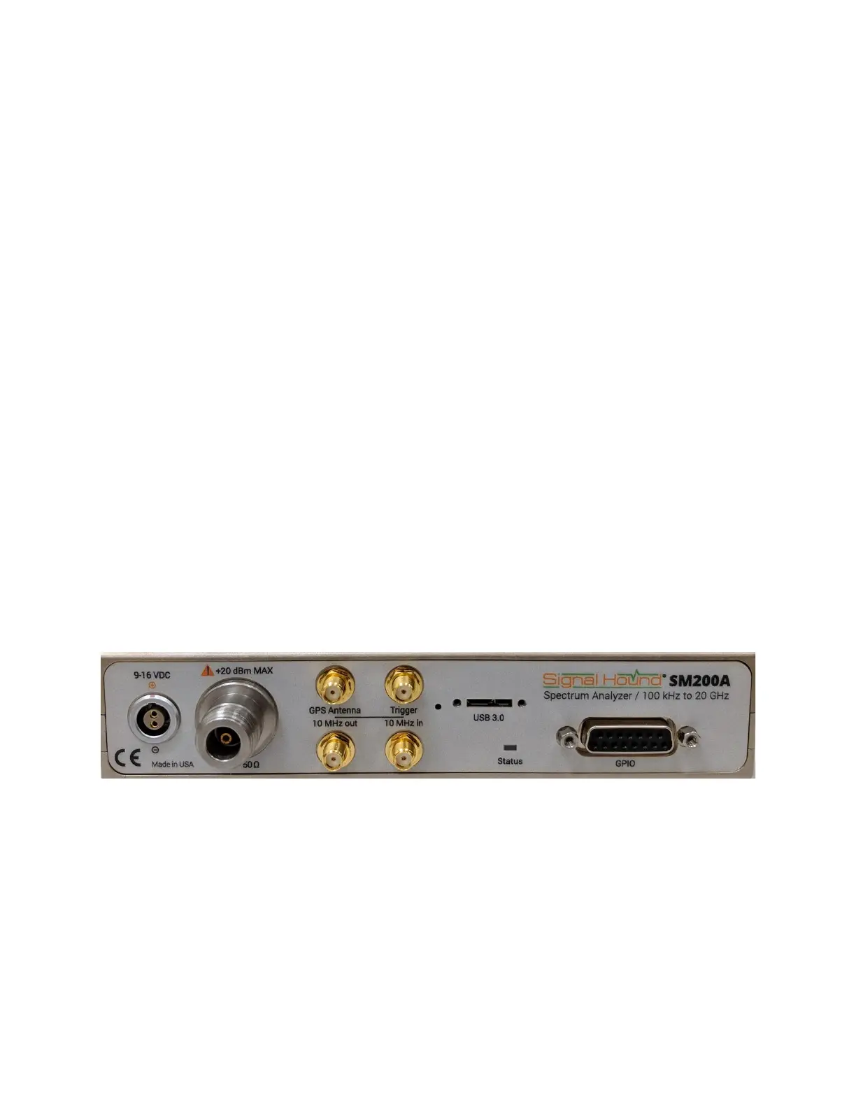
2.5 Front Panel
2.5.1 The SM200A/B and SM435B Front Panel
The front panel has 8 connectors:
1. 9-16V DC power input: Use the included 12V supply, or a battery that can source 40 watts.
2. 50Ω RF Input: Do not exceed +20 dBm or damage may occur. This will be type N for the
SM200 and 2.4 mm for the SM435.
3. SMA GPS antenna port: The GPS antenna (included) may be connected here to discipline
the time base and time stamp I/Q data
4. Trigger In: The rising or falling edge of a digital 3.3V or 5V signal may be used to trigger
in I/Q streaming modes.
 Loading...