EasyManua.ls Logo

Signet 2551 User Manual

Signet 2551
12 pages
To Next Page IconTo Next Page
Page #1 background imageLoading...
Page #1 background image
1
2
3
4
JP2
FREQUENCY OUT
SERIAL (S
L) OUT
3
Connect output signals and power
to this 4-terminal block.
1.
Sensor Type Pipe Size Jumper Position
2551-P0/T0/V0/W0 ½ in. to 2½ in.
DN15 to DN65
2551-P0/T0/V0/W0 3 in. to 4 in.
DN80 to DN100
2551-P1/T1/V1/W1 5 in. to 6 in.
DN125 to DN150
2551-P1/T1/V1/W1 8 in.
DN200
2551-P2/T2/V2/W2 10 in. to 12 in.
DN250 to DN300
2.
3.
4.
4.
5.
Signet 2551 Magmeter
*3-2551.090*
3-2551.090 Rev G 10/08 English
1. Quick Start Guide
This manual contains the general installation, wiring and calibration data for the Signet 2551-XX-11 Magmeter with Frequency or Serial
data output, and for the Signet 2551-XX-12 Magmeter with Current output. The basic steps are outlined on this page.
See each referenced section for detailed information.
1. Con gure the Hardware
2551-XX-11 ONLY: Position this Jumper to select
digital (S
3
L) output or Frequency output. (Not used
for Current output version) Sec. 5 Pg. 4
2. Position the PIPE SIZE Jumper according to your
pipe size. Sec. 5 Pg. 4.
3. Install the Magmeter into the pipe.
Use Signet installation ttings ONLY.
The installation tting is critical to Magmeter
performance. Sec. 3 Pg. 3
4. Connect POWER and OUTPUT wiring.
2551-XX-11 Frequency out: Sec. 8.1 Pg. 6
2551-XX-11 Serial data out: Sec. 8.2 Pg. 6
2551-XX-12 Current out wiring: Sec. 7 Pg. 5
GROUNDING
Without a good Earth Ground, the Magmeter may
not operate ef ciently. Sec. 6 Pg. 5
5. Route the wiring out through the two cable ports.
Use appropriate hardware to secure the 2551 from
moisture intrusion. One Liquid Tight Connector is
included. Sec. 5 Pg. 4
Topic: Page
1. Quick Start Guide 1
2. Speci cations 2
3. Installation: Pipe Fittings 3
4. Selecting a Location 3
5. Hardware Con guration 4
6. General Installation and Grounding Tips 5
7. Wiring the Magmeter with 4-20 Loop 5
Topic: Page
8. Wiring the Magmeter
with Frequency or Digital Output 6
9. Calibration and Software Con guration 6
10. Calibration Data 7
11. Maintenance and Troubleshooting 11
12. Ordering Information 12
English
Description
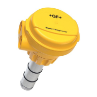
The Signet 2551 Magmeter is an insertion style magnetic ow sensor. The patented sensor design is available in a variety of corrosion-
resistant materials to provide long-term reliability and minimal maintenance costs. Wetted material combinations include PP/316 SS,
PVDF/SS, PVDF/Hastelloy-C, and PVDF/Titanium. The 2551 installs quickly and securely into a wide selection of ow ttings to deliver
accurate ow measurement in pipe sizes ranging from DN15 to DN300 (½ in. to 12 in.).
Signet 2551 Magmeters are available with a frequency output or a 4 to 20 mA output. Signet's digital (S
3
L) output is included with the
Frequency output models for use with the Signet 8900 Multi-Parameter Controller, while the 4 to 20 mA output can be used for a direct
input to a PLC, SCADA or telemetry system.
All 2551 Magmeters feature empty pipe detection and LED-assisted diagnostics. The Signet 3-0250 USB to Digital S
3
L set-up tool is
available to customize every performance feature in the 2551 to adapt it to the speci c application requirements.

Questions and Answers:

Signet 2551 Specifications

General IconGeneral
Repeatability±0.5% of reading
Material CompatibilityConductive liquids
Output4 to 20 mA, frequency
Power24 VDC
Resolution0.001 m/s (0.003 ft/s)
Pipe Size RangeDN15 to DN900 (0.5 to 36 in.)

Summary

Quick Start Guide

Specifications

General Specifications

Covers pipe size range, flow range, linearity, repeatability, and minimum conductivity.

Wetted Materials

Lists material combinations for sensor body, electrodes, grounding ring, and O-rings.

Electrical Specifications

Details power requirements for different outputs and current/frequency output specs.

Environmental Requirements

Covers storage temperature, humidity, ambient, operating temperature, media, and pressure limits.

Standards and Approvals

Lists CE, NEMA 4X/IP65, EMC, Safety standards, and U.S. Patent.

Installation: Pipe Fittings

Plastic Installation Fittings

Describes plastic tees, glue-on saddles, clamp-on saddles, and metric union tees.

Metal Installation Fittings

Describes iron, carbon steel, 316 SS threaded tees, weld-on weldolets, and fiberglass fittings.

Selecting a Location

Flow Profile Requirements

Explains the need for a full pipe and developed turbulent flow profile.

Installation Considerations

Covers conduit port orientation, chemical injection, and gravity flow systems.

Hardware Configuration

Jumper Settings

Explains the function of JP2 jumper for output selection and pipe size.

Terminal Connections

Details connecting output cables to the 4-terminal block and sensor wiring.

General Installation and Grounding Tips

Sensor Conditioning

Advises on allowing the sensor to soak in a full pipe for stable performance.

Grounding

Explains grounding requirements to eliminate electrical interference.

Wiring the 4-20 mA Loop Output

Wiring the Frequency or Digital (S³L) Output

Frequency Output Wiring

Details connecting frequency output to Signet instruments and other manufacturers.

S³L Output Wiring

Describes connecting S³L output to the Signet 8900 Multi-Parameter Controller.

Calibration and Software Configuration

Parameter Customization

Lists customizable parameters like 4-20 mA span, noise rejection, low flow cutoff, averaging, and sensitivity.

Calibration Data: Plastic and Metal Fittings (Inch)

Plastic Installation Fittings (Inch)

K-factors and 20mA values for PVC, CPVC, Polypropylene tees and saddles.

Metal Installation Fittings (Inch)

K-factors and 20mA values for Iron, CS, SS tees and weld-o-lets.

Calibration Data: Metric Plastic Fittings

Plastic Installation Fittings (Metric)

K-factors and 20mA values for metric PP, PVDF, PVC fittings.

Calibration Data: Metal Fittings (Inch - Part 1)

Carbon Steel Tees and Weld-o-Lets

K-factors and 20mA values for Carbon Steel tees and weld-o-lets.

Stainless Steel Tees and Weld-o-Lets

K-factors and 20mA values for Stainless Steel tees and weld-o-lets.

Galvanized Iron Tees

K-factors and 20mA values for Galvanized Iron tees.

Calibration Data: Metal Fittings (Inch - Part 2)

Iron Saddles

K-factors and 20mA values for Iron Saddles.

Bronze and Copper Tees and Brazolets

K-factors and 20mA values for Bronze and Copper fittings.

Maintenance and Troubleshooting

Maintenance

Recommends cleaning electrodes and avoiding abrasive materials.

Troubleshooting

Lists common symptoms, causes, and solutions for erratic output or incorrect readings.

Troubleshooting with LED Indicators

Explains the meaning of different LED light combinations for status indication.

Ordering Information

Sensor Part Number Structure

Details how to construct the part number based on materials, pipe size, and output.

Replacement Parts and Accessories

Lists available replacement parts like O-rings and accessories like power supplies and tools.