WARNING!
• Remove power to unit before wiring input and out-
put connections.
• Follow instructions carefully to avoid personal
injury.
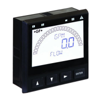
Signet 8550-1 Flow Transmitter
Contents
1. Specifi cations
2. Installation
3. Electrical Connections
4. Menu Functions
Current output:
• 4 to 20 mA, isolated, fully adjustable and reversible
• Max loop impedance: 50 Ω max. @ 12 V
325 Ω max. @ 18 V
600 Ω max. @ 24 V
• Update rate: 100 ms
• Accuracy: ±0.03 mA
Open-collector output, optically isolated:
• 50 mA max. sink, 30 VDC maximum pull-up voltage.
• Programmable for:
• High or Low setpoint with adjustable hysteresis
• Pulse operation (max rate: 300 pulses/min).
Environmental
• Operating temperature: -10 to 70°C (14 to 158°F)
• Storage temperature: -15 to 80°C (5 to 176°F)
• Relative humidity: 0 to 95%, non-condensing
• Maximum altitude: 2000 m (6562 ft)
• Insulation category: II
• Pollution degree: 2
Standards and Approvals
• CE, UL listed
• Immunity & Emissions: EN61326
• Manufactured under ISO 9001 and ISO 14001
General
Compatibility: Signet Flow Sensors (w/freq out)
Enclosure:
• Rating: NEMA 4X/IP65 front
• Case: PBT
• Panel case gasket: Neoprene
• Window: Polyurethane coated polycarbonate
• Keypad: Sealed 4-key silicone rubber
• Weight: Approx. 325g (12 oz.)
Display:
• Alphanumeric 2 x 16 LCD
• Update rate: 1 second
• Contrast: User selected, 5 levels
• Display accuracy: ±0.5% of reading @ 25ºC
• Thermal sensitivity shift: ±0.005% of reading per ºC
Electrical
• Power: 12 to 24 VDC ±10%, regulated
61 mA max current
Sensor Input:
• Range: 0.5 to 1500 Hz
• Sensor power: 2-wire: 1.5 mA @ 5 VDC ± 1%
3 or 4 wire: 20 mA @ 5 VDC ± 1%
Optically isolated from current loop
• Short circuit protected
Flow 6.25 GPM
Total 1234567.8>
ENTER
Signet Flow
Transmitter
2. Installation
ProcessPro transmitters are available in two styles: panel mount and fi eld mount. The panel mount is supplied with the necessary
hardware to install the transmitter. This manual includes complete panel mounting instructions.
Field mounting requires one of two separate mounting kits. The 3-8051 integral kit joins the sensor and instrument together into a single
package. The 3-8050 Universal kit enables the transmitter to be installed virtually anywhere.
Detailed instructions for integral mounting or other fi eld installation options are included with the 3-8051 Integral kit or the 3-8050
Universal kit.
SIDE VIEW
Field Mount w/
8051 Integral kit
102 mm
(4.0 in.)
96 mm
(3.8 in.)
SIDE VIEW
Field Mount w/
8050 Universal base
106 mm
(4.18 in.)
82 mm
(3.23 in.)
92 mm
(3.6 in.)
97 mm
(3.8 in.)
56 mm
(2.2 in.)
41 mm
(1.6 in.
)
Optional
Rear
Cover
Panel Mount
SIDE VIEW
FRONT VIEW
96 mm
(3.8 in.)
96 mm
(3.8 in.)
Field Mount &
Panel Mount
1. Specifi cations
Dimensions
3-8550.090-1 Rev L 6/06 English
*3-8550.090-1*
English
CALL 1-800-577-8111 FOR SALES AND SUPPORT
CALL 1-800-577-8111 FOR SALES AND SUPPORT
CLICK HERE TO RETURN TO WEBSITE
CLICK HERE TO RETURN TO WEBSITE