AP09 Datum 04.05.2000 Art.Nr. 78091 Z.Nr. 8665013 Änd.Stand 140/00 9
ENGLISH
1. Safety information
In order to carry out installation correctly, we
strongly recommend this document is read very
carefully. This will ensure your own safety and
the operating reliability of the device.
• Your device has been quality controlled, te-
sted and is ready for use. Please respect all
warnings and information which are marked
either directly on the device or in this document.
• Warranty can only be claimed for components
supplied by SIKO GmbH. If the system is used
together with other products, the warranty for the
complete system is invalid.
• Repairs should be carried out only at our
works. If any information is missing or unclear,
please contact the SIKO sales staff.
2. Identification
Please check particular type of unit and type
number from the identification plate.Type num-
ber and the corresponding execution are indica-
ted in the delivery documentation.
e.g. AP09-0023
type number
type of unit
3. Installation
The unit should be used only according to the
protection level provided. Protect the unit, if
User Information
AP09
Absolute / Incremental Electronic
Position Indicator
necessary, against environmental influences
such as sprayed water, dust, knocks, extreme
temperatures.
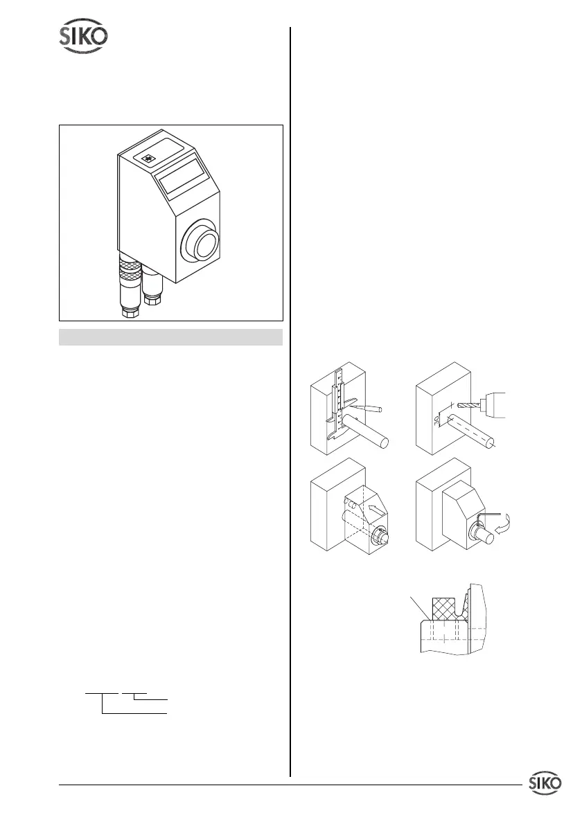
Slide AP09 onto the solid shaft, insert torque pin
into the prebored mounting hole and use grub
screw M5 to fix the AP09's hollow shaft to the
machine's solid shaft (see fig. 1).
• Ensure sliding fit between solid shaft and AP09.
• Ensure accurate shaft alignment and mount
the AP09 without force. Do not exceed the
values for the maximum axial and radial shaft
load. If the shaft is not correctly aligned, strain
on the bearings will result, which may cause
overheating and irreparable damage.
• Especially when using torque pin type A for
fixing, ensure that AP09 does not jam and that
it is mounted without strain. Please remember
this when choosing the AP09's bore diameter.
• Knocks on the unit should be avoided!
• Make sure that the axial seal is correctly
mounted ! (see fig. 2)
Fig. 1: Mounting instructions
Fig. 2: Axial seal
4. Electrical connection
• Switch power off before any plug is inserted or
removed.
• Wiring must only be carried out with power off.
• Provide standed wires with ferrules.
• Check all lines and connections before swit-
Torque pin type A : pin ø 6 h9
type B : bore ø 10 +0.8
Grub screw has to
be screwed in flush
to surface
 Loading...