8 MSK320+MB320,MRI01,MR320,MRF320 Datum 23.11.2009 Art.Nr. 80353 Änd. Stand 350/09
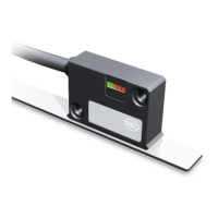
Fig. 2 Fig. 3
Fig. 4 Fig. 5
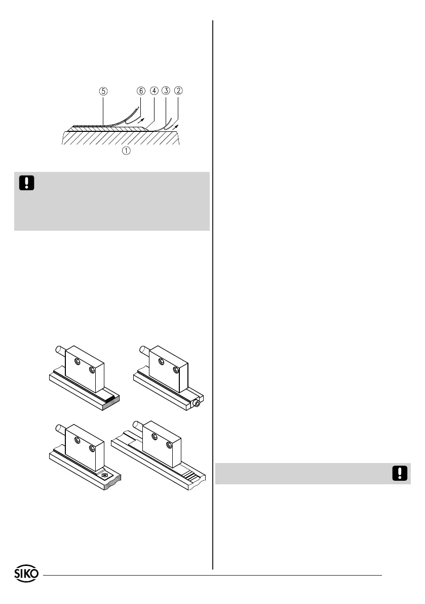
Fig. 1: Mounting of the magnetic strip
Remove protective foil (6) from adhesive tape on
the cover strip (5).
Fix cover strip (both ends should slightly over-
lap).
Also fix cover strip's ends to avoid unintenti-
onal peeling.
•
•
•
Avoid knocks on the magnetic ring.
Provide for a relief groove in the solid shaft
(see fig. 6).
3.3 Mounting of the magnetic ring MRF320
Glue type "UHU Endfest 300" (or similar one) is
used to fix magnetic ring MRF320 to the shaft.
To ensure a concentric running of magnetic ring
MRF320 the glueing surface should be keywaylike.
Make sure that the glue is only inside the keyway.
Apply glue and then immediately fix magnetic ring.
Please also observe glue manufacturer's instruc-
tions regarding hardening time (24 hours).
3.4 Mounting of the magnetic ring MR320
Slide magnetic ring MR320 onto the shaft and
then tighten grub screw M6 to fix it to the shaft.
Ensure sliding fit between shaft and MR320.
Mount MR320 without force and without strain.
Possible forces should go to the metal flange.
Avoid knocks on the magnetic ring.
Provide for a relief groove in the solid shaft
(see fig. 6).
3.5 Mounting of the magnetic sensor MSK320
The magnetic sensor MSK320, design F, can be
mounted e.g. to a mounting square with a corre-
sponding mounting bore by tightening the two
nuts M8x0,5n.
The magnetic sensor MSK320, design A+AM can be
fastened by using two bolts M3 over the ø3,5mm
through holes. We recommend to use the enclosed
fixing screws and washer springs (fastening torque
design A=0,25Nm, design AM=1Nm).
Cables should be layed in such a way that there
is no danger of damaging. Provide ten-sion relief
and drag chain or casing, if necessary.
Observe the correct alignment with regard
to the counting direction (fig. 6 and 7). This
does not apply if the counting direction can be
reversed in the electronic interpretation (e.g. in
SIKO's magnetic-strip displays).
Attention! The tolerance and gap measures must
be observed over the whole measuring length.
•
•
•
•
•
•
•
Attention! Do not expose the system to magne-
tic fields. Any direct contact of the magnetic strip
with magnetic fields (e.g. adhesive magnets or
other permanent magnets) is to be avoided. Sen-
sor movements during power loss are not captured
by the follower electronics.
Mounting examples
Mounting with chamfered ends (fig. 2) is not re-
commended unless the strip is installed in a safe
and protected place without environmental influ-
ences. In less protected mounting places the strip
may peel. There we recommend mounting accord.
to fig. 3 and 4.
Mounting in a groove (fig. 5) best protects the
magnetic strip. The groove should be deep enough
to totally embed the magnetic strip.
3.2 Mounting of the magnetic ring MRI01
Slide magnetic ring MRI01 onto the shaft and then
tighten grub screw M4 to fix it to the shaft.
Ensure sliding fit between shaft and MRI01.
Mount MRI01 without force and without strain.
Possible forces should go to the metal flange.
•
•