WIRINGINSTALLATION
WARNING:IsolatefromPowerSupplybeforecommencingwork
WIRINGREQUIREMENTSFORDOMESTICELECTRICFANS
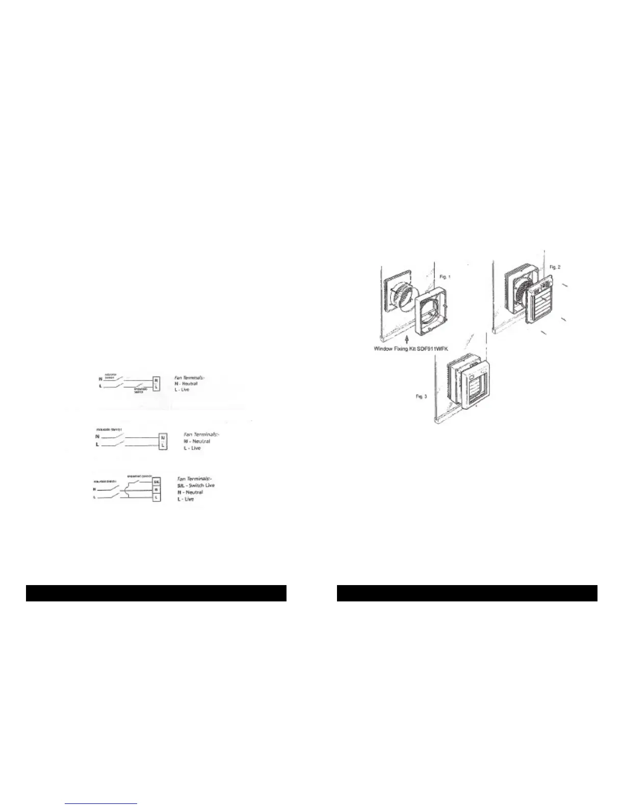
It is recommended that fans be connected into the lighting circuit, with double pole
(3mm) isolation provided before the room light switch and suitably fused, in accordance
with IEE Regulations.
Window Fans should be connected to power supply using a flexible cord with conductors
of between 0.75mm
2
and 1.5mm
2
only.
Wall and ceiling mounted fans for fixed wiring should be connected to the power supply
via a cable with solid conductors of 1mm
2
to 1.5mm
2
only.
IFINDOUBTCONSULTAQUALIFIEDELECTRICIAN
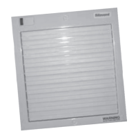
WINDOWFITTING
Strip the fan unit to it’s three components as described on page 4. Cut 184mm (7
1
/
4
”)
hole in glass. This job is best done by a glazier.
Fig 1. Remove the 4 brass clamp nuts from the fixing kit then insert the discharge
grille spigot through the hole from the outside. Locate the surface mounting
housing over the studs. Make sure that the weather seals are not displaced.
Fit clamp nuts. Do not over-tighten.
Fig 2. Insert power supply flex through entry at the top of the surface mounting
housing and through the access hole in the main fan chassis. Fit the main fan
chassis to the surface mounting housing. Refer to Page 7 for wiring.
Fig 3. Once wiring is complete, fit the front cover.
DONOTFORCETHESHUTTERSOPENORCLOSEDAS
THISWILLDAMAGETHESHUTTERMECHANISM
NOTE: Models SVC150TB & SVC150HTB feature a useful short run facility. This
is operated via the built in pull-cord switch. When used the fan will operate
for the time set into it’s integral timer then turn itself off. The fan cannot
be turned off using the switch. The short run facility is not intended to be
used as the main operating switch.
WARNING:ISOLATEELECTRICITYBEFORESTARTINGWORK WARNING:ISOLATEELECTRICITYBEFORESTARTINGWORK
MODELSVC150B
MODELSVC150PB,SVC150HB,SVC150PBTW,SVC150HBTW
MODELSVC150TB,SVC150HTB