WALLFIXINGKITSVC901W
We recommend the use of this fixing kit as it contains all the necessary parts to surface
mount or flush fit the SVC6 fan unit.
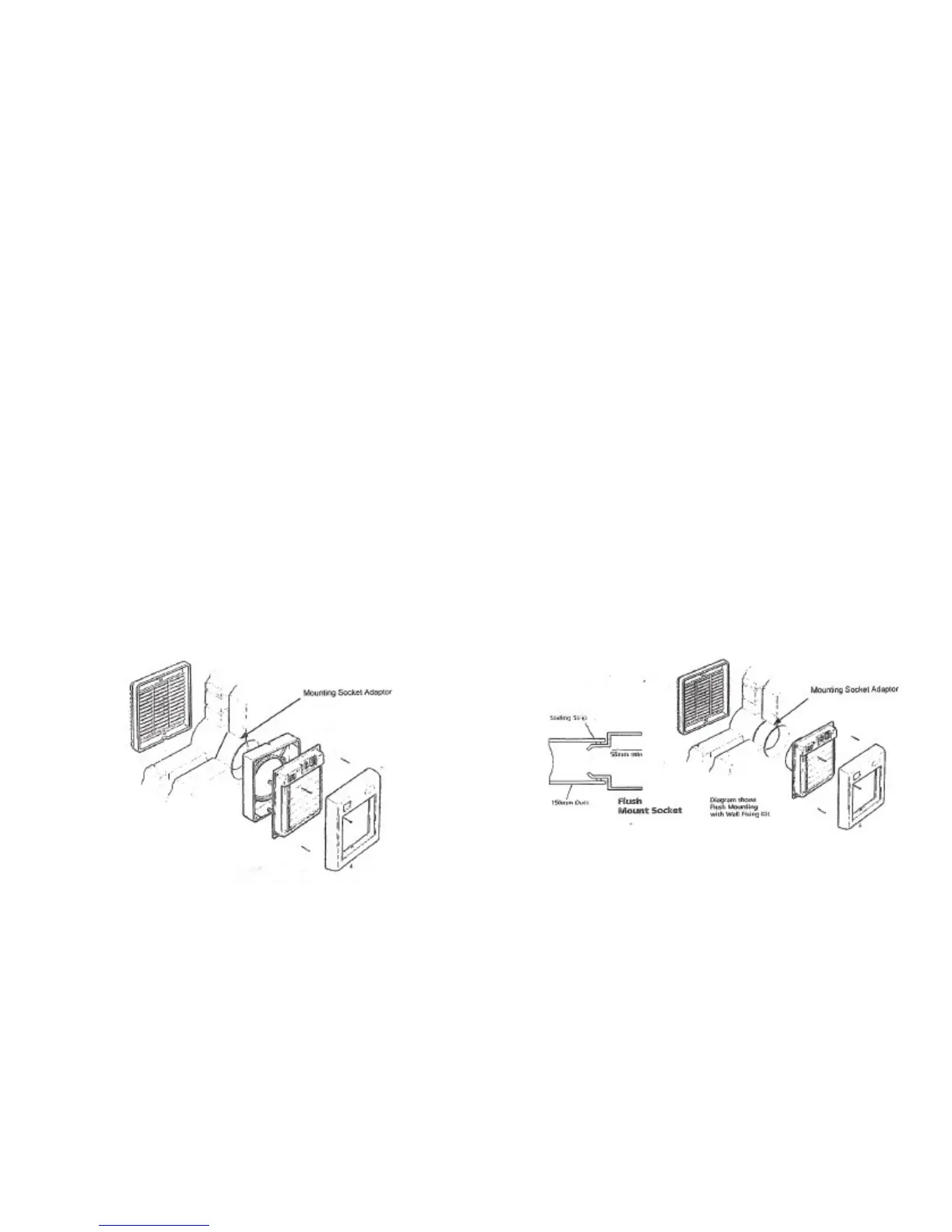
SURFACEMOUNTING
Cut a hole through wall in desired position to take the 150mm duct supplied in the fixing
kit. It is important that there is at least a 5º downward slope towards the outside to allow
for condensation drainage.
The duct should be cut so that it is flush with both sides of the wall less 60mm which is
the length of the mounting socket adaptor body.
Strip the fan to its four main components as described on page 4. The outside grille
should be fitted into the discharge duct and secured to the outside wall using the wall
plugs and screws supplied with the fixing kit. At this point check that the 6” ducting and
mounting socket adaptor are flush with the inside wall before completing installation.
Use the surface mounting housing as a template to mark the fixing screws and cable
entry positions on the inside wall. Make sure surface mounting housing is accurately
lined up with discharge duct and adaptor.
Fix the surface mounting housing to the wall using the wall plugs and screws supplied
with the fixing kit ensuring that the electrical cable is through the cable entry hole in the
surface mounting housing.
Fit the fan into the surface mounting housing and make electrical connections as described
on pages 8 and 9 and refit front cover.
FLUSHMOUNTING
Cut hole through wall in desired position. On the outside allow clearance for the 150mm
duct and on the inside allow clearance for the flush mount socket, this is a little larger
than the duct. It is important that there is a downward slope towards the outside to allow
for condensation drainage.
When the hole through the wall is complete, a length of adhesive sealing strip should be
fixed around the flush mount socket spigot. Now insert the flush mount socket into one
end of the 150mm duct and fit the assembly into position temporarily and mark duct for
cutting to length. If surface mount socket requires trimming, ensure that a depth of at
least 55mm is retained. The duct assembly should be flush with both sides of the wall.
When length is correct, grout the assembly firmly into position.
Strip the fan to its four main components as described on page 4. Assemble the fan as
previously detailed for surface mounting but discard the surface mounting housing and
complete the installation as previously described.
Note: When flush mounting the fan unit the power supply cable must be chased into
the wall surface. Apply the self adhesive sealing strip around the fan chassis
spigot before fixing to socket using wall plugs and screws supplied with fixing
kit.
Make electrical connections as described on page 8. Refit front cover.
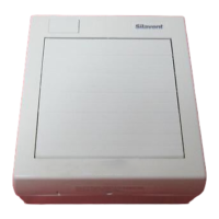
Diagram is for illustration
purposes only. The fan purchased
may vary in looks from the diagram.
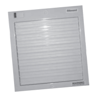
Diagram is for illustration
purposes only. The fan purchased
may vary in looks from the diagram.
 Loading...