Air4 Universal Receiver
Copyright Silca S.p.A 2020. All right reserved
5
English
2. Consult the manual of the original system to idenfy the terminals relang to the power supply
and the appropriate relay contacts. The load connected to the relay contacts must be connected
with the appropriate precauons against re and electric shock respecng the maximum load
values imposed 3A (230 Vac).
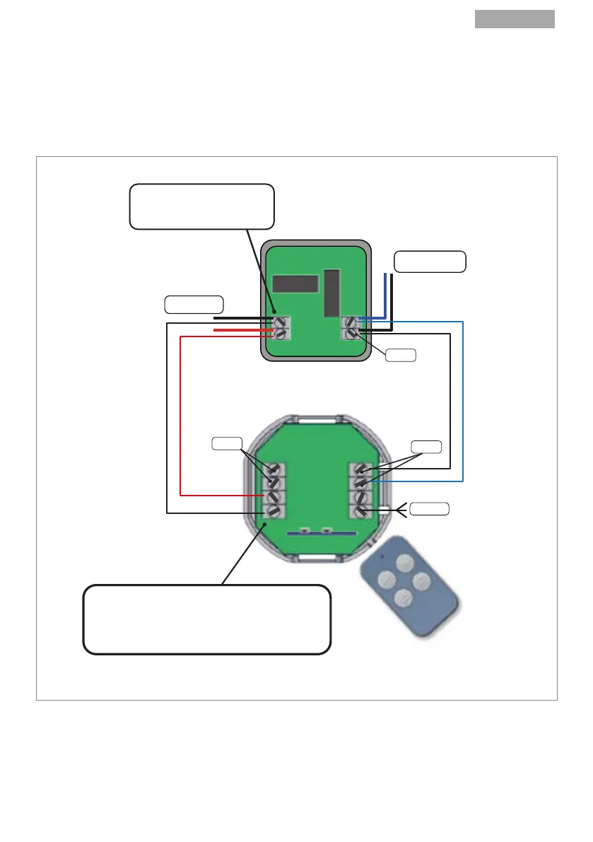
3. Connect 2 suitable wires to the power supply terminals (Fig.1- F) on the Universal Receiver and 2
wires to either the relay terminal 1 or the relay 2 terminals (Fig.1- H; G).
4. Connect the 4 wires in parallel to the appropriate terminals on the exisng electronic board.
Consult the original manual if necessary.
FIG.4
Note: Make sure the receiver antenna wire is not twisted and/or bent; to ensure the best signal it
must be as straight as possible.
5. Your gate, overhead door or barrier is now ready for opening and closing with your Silca remote
control.
Switch on the power supply. The Silca Air4 Universal Receiver is now ready to work.
EXISTING AUTOMATION
ELECTRONIC CARD
POWER SUPPLY
12/24V
FROM EXISTING
GATE SYSTEM
RELAY 2
THE POLARITY INDICATED
ON THE EXISTING RECEIVER
IS MERELY INDICATIVE.
+
-
AIR4 UNIVERSAL
RECEIVER
RELAY 1
RELAY 2
ANTENNA
AIR4 UNIVERSAL RECEIVER POWER SUPPLY TERMINALS
ARE WITHOUT POLARITY (POWER SUPPLY (+) CAN BE
CONNECTED TO EITHER TERMINAL,
AT THE USER’S DISCRETION)
1
2
3
4