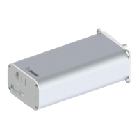
The Silent Gliss 9060 Motor – System 5600 is an advanced motor designed for curtain and blind systems, offering both manual and automatic limit setting capabilities, as well as integration with various radio control modules. This system is engineered for reliable and precise operation in dry room environments.
Function Description
The Silent Gliss 9060 Motor is primarily used to automate the opening and closing of curtain tracks. It features a robust design with various control elements for programming and operation. The motor can be controlled via low-voltage switches, programming buttons, and integrated radio modules, allowing for flexible integration into different home automation or commercial setups. It supports both single and simultaneous open/close operations, making it versatile for various curtain configurations. The system also includes "Touch & Go" and "Manual Override" features, enhancing user convenience and control.
Important Technical Specifications
Motor Specifications:
- Operating Temperature Range: 0°C to +60°C for unrestricted operation of rated data; -20°C to +70°C for storage.
- Protection Class: IP40, indicating protection against solid objects larger than 1mm, but no protection against liquids. This means it is suitable for operation in dry rooms.
- Nominal Voltage: 100-250 VAC / 50-60 Hz. This wide voltage range makes it adaptable to various electrical systems.
- Max. Current: 0.5 A at 240V, 1.3 Amp at 110V.
- Max. Speed: 160 min⁻¹.
- Max. Track Length: 25 m. This specifies the maximum length of the curtain track the motor can effectively operate.
- Max. Torque: 2.4 Nm.
Control Elements:
The motor features several key control elements located on its underside:
- Programming Button A (Green Button): Used for automatic limit setting.
- LED (Green): Indicates the status during automatic programming.
- Low-Voltage Switch: Provides an interface for low-voltage control signals.
- Power Plug (100-250 VAC): For connecting the main power supply.
- LED (Yellow): Indicates the status during manual programming.
- Programming Button M (White Button): Used for manual limit setting.
- Plug Extension Module: Allows for additional module connections.
- DIP-Switch: A set of switches used to configure various operational modes and settings.
DIP-Switch Settings:
The DIP-switches allow for customization of the motor's behavior:
- Position 1 (X-X-X): Latching (1) or non-latching (0) operation.
- Position 2 (X-X-X): Non-latching (0) or latching (1) operation.
- Position 3 (X-1-X): Touch & Go and Manual Override on.
- Position 4 (X-0-X): Touch & Go and Manual Override off.
- Position 5 (X-X-1): Revolution 160 min⁻¹.
- Position 6 (X-X-0): Revolution 120 min⁻¹.
- Position 7 (1-1-1): Default setting.
- Key: 1 = on, 0 = off.
Low Voltage Switch Connections (Pin-outs):
- Pin 1: Common / +24V.
- Pin 2: Open - single.
- Pin 3: Close - single.
- Pin 4: Open - simultaneous.
- Pin 5: Close - simultaneous.
- Pin 6: GND.
The 24V output is used for volt-free / dry contact switching, with specific DIP switch settings required for motor control.
Usage Features
Limit Setting:
The motor supports two primary methods for setting end limits:
-
Manual Limit Setting (White M button):
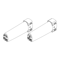
- This method is used when the 5600 system is supplied in a single piece and limits need adjustment, or when the system is assembled from multiple parts.
- Requires a 0997 setting lead or other control devices (standard mains test lead, radio wall switch, dry contacts, handheld transmitter).
- Procedure:
- Plug in the power lead.
- Press the white button for 1 second.
- Using the 0997 setting lead (or other control), push and hold the button in the first direction until the desired end position is reached (minimum movement of 500 mm). Release the button. The yellow LED will light when a direction button is pressed.
- Push and hold the button for the opposite direction until the second end position is reached. Release.
- Push the button in the first direction and hold until the movement stops automatically. Release. The yellow LED will turn off, indicating the motor is ready for use.
-
Automatic Limit Setting (Green A button):
- This method is used when the 5600 system is supplied in two or more parts and limits need to be set after assembly.
- Procedure:
- Ensure the 10725 card is inserted to enlarge the stack.
- Apply permanent power to the motor.
- Press the green button for 1 second; the green LED will flash.
- The motor will automatically set the end limits in sequence.
- Remove the 10725 card.
- The motor is ready for use when the green LED stops flashing.
Radio Control Integration:
The Silent Gliss 9060 Motor can be integrated with various radio modules for remote control.
Maintenance Features
The manual does not explicitly detail maintenance features. However, the design implies ease of access for programming and troubleshooting:
- Accessible Control Elements: All programming buttons, LEDs, DIP-switches, and power connections are located on the underside of the motor, making them easily accessible for setup and adjustments.
- Diagnostic LEDs: The green and yellow LEDs provide visual feedback during programming, which can assist in diagnosing issues during setup.
- Clear Programming Steps: The detailed, step-by-step instructions for limit setting and radio control addressing simplify the installation and configuration process, reducing the likelihood of errors that might require maintenance.
- Modular Design: The "Plug extension module" suggests a modular design, potentially allowing for easy replacement or addition of components.
- Dry Room Operation: The IP40 protection class emphasizes the need for operation in dry environments, which is a key factor in preventing damage and ensuring longevity.