EasyManua.ls Logo

SILENT KNIGHT 5104 User Manual

SILENT KNIGHT 5104
44 pages
To Next Page IconTo Next Page
Page #1 background imageLoading...
Page #1 background image
151053 i
Content
Section 1
Introduction
.............................................................................................................................................. 1-1
1.1 Feature ......................................................................................................................................................1-1
1.2 Accessory Devices ................................................................................................................................... 1-2
1.3 About This Manual .................................................................................................................................. 1-2
1.3.1 How to Use This Manual .................................................................................................................. 1-2
Section 2
Agency Requirements
............................................................................................................... 2-1
2.1 Telephone Requirements .......................................................................................................................... 2-1
2.2 FCC Warning ........................................................................................................................................... 2-2
2.3 UL Requirements .....................................................................................................................................2-2
Section 3
Installation
................................................................................................................................................. 3-1
3.1 Electrical Specifications ........................................................................................................................... 3-1
3.2 Environmental Specifications .................................................................................................................. 3-1
3.3 Wiring Specifications ............................................................................................................................... 3-2
3.4 Panel Description ..................................................................................................................................... 3-3
3.4.1 Terminal Description ........................................................................................................................ 3-4
3.4.2 LED Descriptions ............................................................................................................................. 3-5
3.4.2.1 Externally Visible LEDs (L3, L4, & L5) ............................................................................... 3-5
3.4.2.2 Phone Line Fault Indicator LEDs (L6 &L7) .......................................................................... 3-5
3.4.2.3 Overcurrent LED Indicators (L1 & L2) ................................................................................. 3-6
3.4.3 Reset / Silence Switch ....................................................................................................................... 3-6
3.4.4 Cable Connectors (P1 & P2) ............................................................................................................. 3-7
3.4.5 On-board Piezo Sounder ................................................................................................................... 3-7
3.5 Calculating Current Draw and Standby Battery ...................................................................................... 3-8
3.5.1 Worksheet Requirements .................................................................................................................. 3-8
Fill in the Current Draw Worksheet (Table 3-5) in section 3.5.2. ................................................ 3-8
3.5.2 Current Draw Worksheet .................................................................................................................. 3-9
3.5.2.1 Maximum Battery Standby Load ......................................................................................... 3-10
3.6 Mounting the 5104 Cabinet .................................................................................................................... 3-11
3.7 Battery Connection ................................................................................................................................ 3-11
3.8 Detector Installation ............................................................................................................................... 3-12
3.8.1 Class A (Style D) Zones ................................................................................................................. 3-12
3.8.2 Class B (Style B) Zones ................................................................................................................. 3-13
3.8.3 Four-Wire Smoke Detector Connection ......................................................................................... 3-14
3.8.4 Connecting the 7181 Zone Converter ............................................................................................. 3-15
3.9 Auxiliary Notification Appliance Installation ........................................................................................ 3-16
3.9.1 Non-Supervised Notification Appliance Wiring ............................................................................ 3-16
3.9.2 Supervised Notification Appliance Wiring ..................................................................................... 3-17

Table of Contents

Questions and Answers:

SILENT KNIGHT 5104 Specifications

General IconGeneral
BrandSILENT KNIGHT
Model5104
CategoryCell Phone
LanguageEnglish

Summary

Section 1 Introduction

1.1 Features of the 5104 Fire Communicator

Details the key features and capabilities of the 5104 Fire Communicator, including zone supervision and reporting formats.

1.2 Accessory Devices for the 5104

Lists optional accessory devices that can be used with the 5104 Fire Communicator, such as remote annunciators.

1.3 About This Manual

Provides information about the purpose and intended audience of the installation manual.

1.3.1 How to Use This Manual

Explains the conventions used within the manual, including page numbering and text formatting.

Section 2 Agency Requirements

2.1 Telephone Requirements for Installation

Outlines the specific telephone line requirements and information needed for the 5104 installation.

2.2 FCC Warning and Compliance

Provides the FCC warning statement regarding radio interference and operational conditions.

2.3 UL Installation Requirements

Details the Underwriters Laboratories (UL) listing and installation requirements for the 5104 system.

Section 3 Installation Procedures

3.1 Electrical Specifications Overview

Lists the electrical specifications for the 5104 Fire Communicator, including AC power and voltage requirements.

3.2 Environmental Specifications and Mounting

Defines the environmental conditions to avoid during installation to prevent damage to the unit.

3.3 Wiring Specifications and Guidelines

Provides guidelines for wiring the 5104 to prevent induced noise and ensure proper function.

3.4 Panel Description and Components

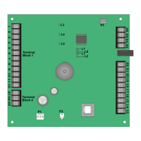
Describes the 5104 circuit board components, including terminal strips, LEDs, switches, and connectors.

3.4.1 Terminal Block Descriptions

Details the function and electrical specification for each terminal on the 5104 panel.

3.4.2 LED Status Indicators

Explains the meaning of each LED on the 5104 panel, including externally visible and internal indicators.

3.4.3 Reset and Silence Switch Functions

Describes the functions of the Reset/Silence switch, including silencing alarms and resetting devices.

3.4.4 Cable Connector Functions

Details the function of the P1 and P2 connectors on the 5104 circuit board.

3.4.5 On-board Piezo Sounder

Explains the function of the on-board piezo sounder for audible trouble and supervisory notifications.

3.5 Calculating Current Draw and Standby Battery

Guides the user on determining the system's current draw and required standby battery capacity.

3.5.1 Worksheet Requirements for Current Draw

Outlines the steps and requirements for filling out the current draw worksheet for battery calculations.

3.5.2 Current Draw Calculation Worksheet

Provides a worksheet to calculate current draw for various devices and determine total system requirements.

3.5.2.1 Maximum Battery Standby Load Limits

Specifies the maximum allowable load for 24 and 60-hour standby periods based on battery size.

3.6 Mounting the 5104 Cabinet

Provides instructions and considerations for securely mounting the 5104 cabinet.

3.7 Battery Connection Procedure

Details the correct procedure for connecting the 12 VDC backup battery to the 5104 system.

3.8 Detector Installation Guidelines

Provides instructions for installing various types of fire detectors with the 5104 system.

3.8.1 Class A (Style D) Zone Wiring

Explains how to wire Class A (Style D) supervised fire loops using normally open contacts.

3.8.2 Class B (Style B) Zone Wiring

Details the wiring procedure for Class B (Style B) fire zones, including EOL resistor placement.

3.8.3 Four-Wire Smoke Detector Connection

Describes the connection method for four-wire smoke detectors using a power supervision module.

3.8.4 Connecting the 7181 Zone Converter

Illustrates how to connect the Model 7181 Zone Converter to configure zone types for the 5104.

3.9 Supplemental Notification Appliance Installation

Provides instructions for installing supplemental notification devices to the 5104 system.

3.9.1 Non-Supervised Notification Appliance Wiring

Details how to wire non-supervised notification devices, such as audible alarms, to the panel.

3.9.2 Supervised Notification Appliance Wiring

Explains how to wire supervised notification devices and the implications of open or shorted conditions.

3.10 Telephone Line Connections

Describes the proper wiring of telephone lines to the 5104 using the Model 7860 cable.

3.11 Model 5230 Remote Annunciator Installation

Provides instructions for installing the optional 5230 Remote Annunciator for system control and programming.

3.11.1 Mounting the 5230 Annunciator

Details the steps for mounting the 5230 remote annunciator to a dual gang electrical box.

Section 4 Slave Fire Communicator Application

Section 5 5230 Operation

5.1 5230 Display Messages and Meanings

Lists and explains the various messages that can be displayed on the 5230 remote annunciator's LCD.

5.2 5230 Touchpad Functions

Describes the functions of each key on the 5230 remote annunciator's keypad for system interaction.

Section 6 Programming the 5104 System

6.1 5230 Remote Annunciator Programming

Covers the programming of the 5104 system using the 5230 remote annunciator.

6.1.1 Default User Codes

Lists the factory default Installer and Operator codes for accessing programming modes.

6.1.2 Entering and Exiting Program Mode

Details the procedure for entering and exiting the system's programming mode.

6.1.3 How to Enter Program Mode

Step-by-step instructions on how to access the programming mode using the 5230.

6.1.4 How to Exit Program Mode

Provides the method to safely exit the programming mode without making changes.

6.1.5 Step-by-Step Programming

Explains that all programming is done in sequential steps, each configuring a specific parameter.

6.1.6 Maneuvering Through Programming

Guides users on efficiently navigating through the programming menu and options.

6.1.6.1 Entering Selected Values

Describes how to enter different types of values, including numeric, Yes/No, and alpha-numeric selections.

6.1.6.2 Bypass a Programming Step

Explains how to skip a programming step by pressing the Enter key without input.

6.1.6.3 Go to a Specific Programming Step

Details how to directly access a specific programming step by its number.

6.1.7 List of Programming Steps

A comprehensive list of all programming steps, their tasks, choices, and default settings.

6.2 Model 5541 Programming Options

Describes remote programming using the 5541 Downloading software and related manuals.

Section 7 Reporting System

7.1 Description of Reporting Formats

Details the five basic reporting formats supported by the 5104 and their characteristics.

7.2 Event and Reporting Codes by Format

Lists events sent by the 5104 and their corresponding codes for each reporting format.

Section 8 Troubleshooting Guide

Related product manuals