INSTALLATION INSTRUCTIONS
A
B
Washer
Tube
Connection
Tubing
Switch
1
2
3
4
5
67
8
9
10
11
13
12
14
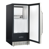
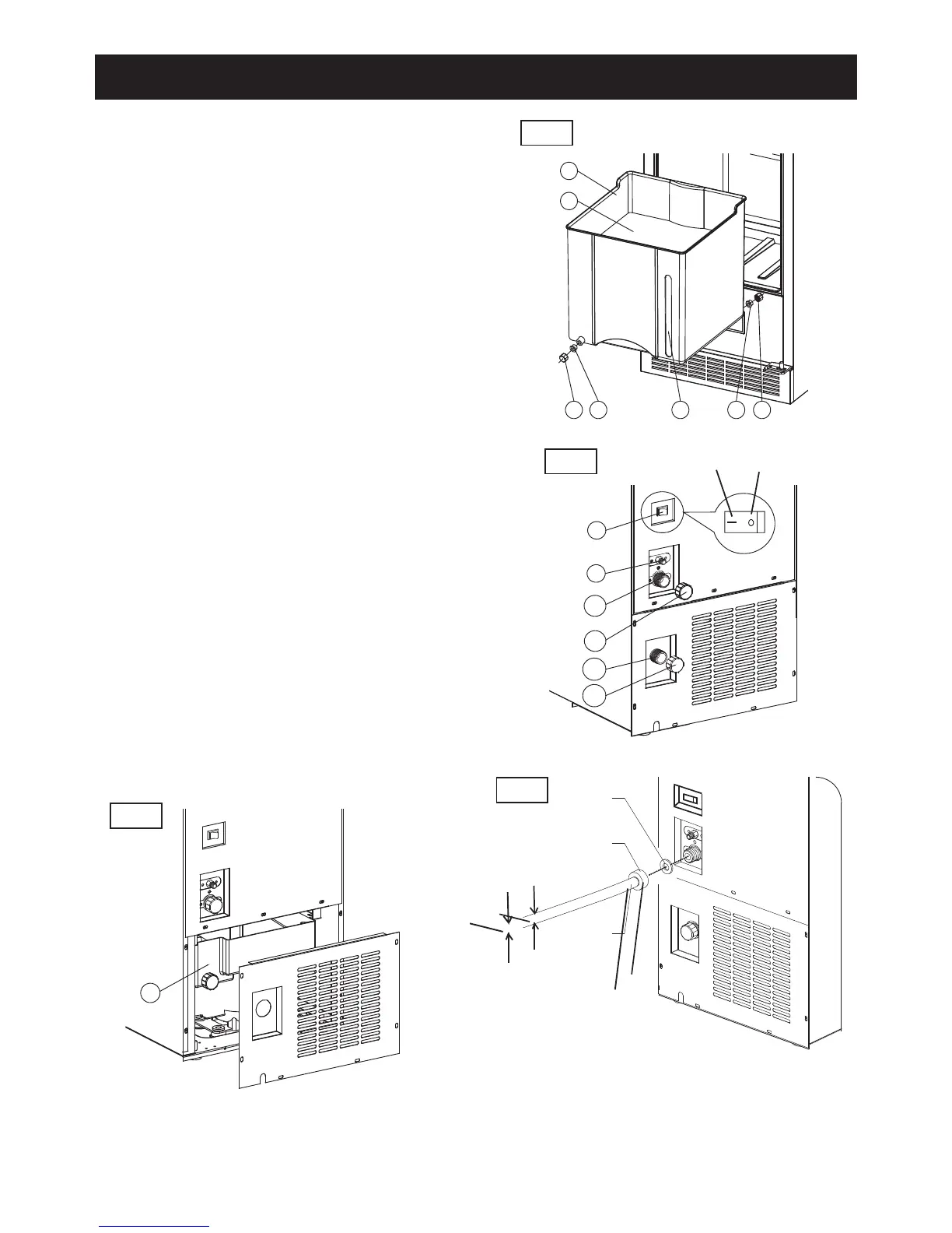
1. Ice bucket: Stores ice
2. Bottom board of ice box: Separate the ice and unneces-
sary water during ice making.
3. Drain nut (front): Stops water from draining through the
front. Please leave nut in place during continuous drain
mode and drain pump mode.
4. Drain seal (front): Stops water from draining through the
front. Please leave nut in place during continuous drain
mode and drain pump mode.
5. Water level sight: Allows you to observe ice level.
6. Drain seal (back): Stops water from draining through the
back. Please leave this in place for manual drain mode.
7. Drain nut (back): Stops water from draining through the
back. Please leave this in place for manual drain mode.
8. Drain pump switch: Turns the drain pump on and off.
9. Water inlet tube connector: Used to connect water supply
line to the ice maker inlet valve.
10. Drain pump outlet: Used to connect the drain hose when
using drain pump mode.
11. Drain pump cap: Used to close the drain pump outlet when
you are not using the drain pump mode.
12. Direct drain cap: To close the outlet if you are not using
continuous drain mode.
13. Continuous drain outlet: To close the outlet if you are not
using continuous drain mode.
14. Drain tank: Stores unnecessary water from the ice maker
when using continuous drain mode.
LOCATION OF PARTS
Fig.B
Fig.D
Fig.E
Garden hose
diameter no
less than 1/2”
Fig.C
ON OFF
Drain Hose
Connection
1’’ N.P.T
4
 Loading...