22
8
DO NOT DUNK ON THIS UNIT .
DO NOT HANG FROM ANY PART OF THIS
UNIT , INCLUDING THE BACKBOARD, RIM,
SUPPORT BRACES OR NET
.
4L-8152-01
WARNING
!
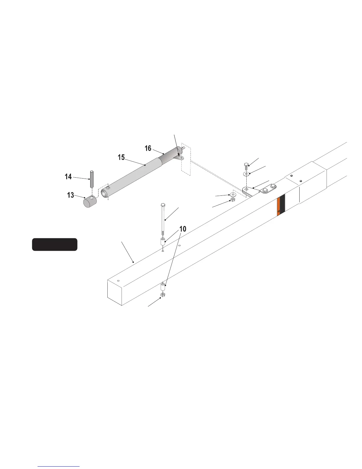
Actuator Tab
6.
5.
NOTE: If necessary, use a rubber mallet
to tap in Pivot Tube (#14)
While still on the two padded saw horses, Slide tab on Actuator (#16) between Post
Ears (#30) and secure using one bolt (#19), two washers (#20) and one lock nut
(#21). Tighten Lock Nut (#21) snug but do not over tighten. See Figure 6.
At this time also tighten nuts (#4) from Step 4.
7.
Secure two stop spacers (#10) to pole, as shown in Figure 6, using one hex
bolt (#22) and one lock nut (#4). Tighten Lock Nut (#4) but do not over
tighten.
If not already pre-assembled, slide Plastic Actuator Sleeve (#15) over Steel Actuator (#16)
and place Actuator Cap (#13) on top. Align holes in all 3 parts and slide Pivot Tube (#14)
through holes in Actuator Cap (#13), Plastic Actuator Sleeve (#15) and Steel Actuator Tube
(#16) until equal amounts stick out through both sides of actuator. See Figure 6.
Figure 6
NOTE: Make sure (#14) Pivot Tube is
installed through all three parts:
1. Actuator Cap (#13)
2. Plastic Sleeve (#15)
3. Steel Actuator Tube (#16)
3
4
20
21
20
19
30
(#22) Bolt goes
in upper hole