nal section of the flue must be fitted
with a static exhaust device that
ensures constant and efficient
extraction of products generated by
combustion;
–to prevent the wind from creating
pressure zones around the chimney
top greater than the uplift force of
combustion gases, the exhaust
outlet should be at least 0.4 m
higher than structures adjacent to
the stack (including the roof top)
within 8 m;
–have a diameter that is not inferior
to that of the boiler union: square or
rectangular-section flues should
have an internal section 10% grea-
ter than that of the boiler union;
–the useful section of the flue must
conform to the following formula:
S resulting section in cm
2
Kreduction coefficient for liquid
fuels:
–0.045 for firewood
– 0.030 for coal
– 0.024 for light oil
– 0.016 for gas
Pboiler input in kcal/h
H height of flue in metres, measu-
red from the flame axis to the
top of the flue reduced by:
–0.50 m for each change of
direction of the connection
union between boiler and flue;
–1.00 m for each metre of
union itself.
2.5 BOILER BODY ASSEMBLY
The boiler body comes supplied assem-
bled. Where there is difficulty in gaining
access to the boiler room, the body can
be supplied in separate sections. For
assembly, proceed as follows:
–prepare the sections, cleaning the
seats of the tapered nipples with
solvent;
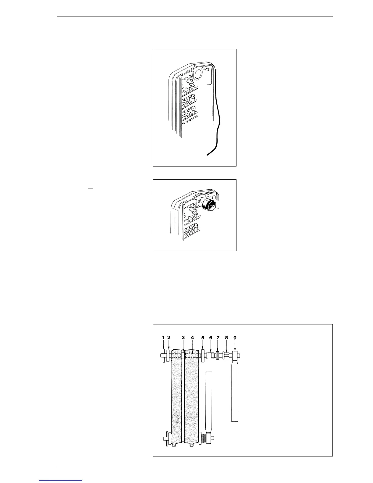
– insert the bead of putty (fig. 5) in the
groove provided for fume tightness,
pressing lightly;
– prepare one of the two intermediate
sections. After lubricating them with
boiled linseed oil, insert the tapered
nipples (fig. 6);
–prepare the head, proceeding as
above, and bring it up to the inter-
mediate section. Add only one sec-
tion at a time;
–
assemble the sections, using the
tools provided consisting of a pair of
staybolts for assembly with the cor-
responding accessories (code
6050900 - fig. 7), exerting pressure
simultaneously on the top hub and
on the bottom hub. If, during this ope-
ration, the sections were to slot
together in such a way as not to be
even and parallel, slide a chisel in the
tighter side and, by applying a little
force, bring the two pieces together
so that they are parallel.
The sections can be considered pro-
perly joined together when their
outer edges come into contact;
– insert the bead of putty in the groo-
ve of the section that has just been
assembled, and then proceed to joi-
ning up the other sections until the
body is completed.
NOTE: before proceeding to con-
nect the system, test the boiler
block with a water pressure of 7.5
bar.
2.6 FITTING THE CASING
The casing and the control panel are
supplied in separate cardboard packa-
ges. The housing package also con-
tains the boiler documents and the
glass wool for insulating the cast iron
body. To fit the casing, proceed as fol-
lows (fig. 8):
– fix the left front side angle bar (2)
and the right front side angle bar (3)
to the upper tie rods using the two
galvanized nuts provided;
– place the front cross bar (4) on the
lower tie rods before securing the
angle bars with the two cap nuts
provided;
– insulate the cast iron body with the
glass wool (1);
– fix the side parts (5) and (6) to the
angle bars using the ten self-tapping
screws provided, and secure them
at the back with the nuts placed on
the tie rods;
28
Fig. 5
Fig. 6
KEY
1 Pin
2Flange ø 35/87
3 Biconical nipples
4Staybolt L. 900 + staybolt L. 980
5Flange ø 50/87
6 Stub
7 Thrust bearing
8 Nut
9Tightening wrench
Fig. 7
P
S=K
√H