76
the requirements of the current stan-
dards, as well as the following practical
pointers:
– With direct intake from outside, when
the pipe is longer than 1 m, you are
recommended to insulate the piping so
as to prevent formation of dew on the
outside of the piping during particularly
hard periods of the year.
–
With the outlet pipe outside the buil-
ding or in cold indoor environments,
insulation is necessary to prevent bur-
ner failure in starting.
In such cases, provide for a condensa-
te-collector system on the piping.
–
If a segment of the flue passes through
a flammable wall, this segment must be
insulated with a glass wool pipe insula-
tor 30 mm thick, with a density of 50
kg/m
3
.
The maximum overall length of the
intake and exhaust ducts depends on
the head losses of the single fittings
installed (excluding the doublers) and
must not be greater than 7.50 mm H
2
O
vers. “25 BF” e 11 mm H
2
O VERS. “30
BF”.
For head losses in the fittings, refer to
Table 1.
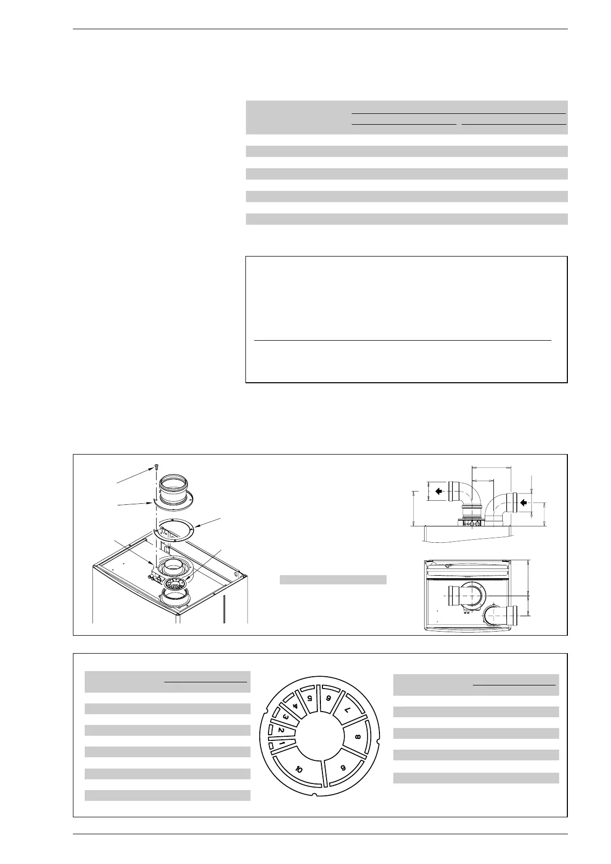
2.8.1 Separate
flue kit (fig. 8)
The separate flue kit code 8089904 is
supplied with an intake diaphragm which
must be used as shown in fig. 8/a, depen-
ding on the maximum load loss permitted
in both flues.
TABLE 1
Accessories ø 80 Load loss (mm H
2
O)
25 BF 30 BF
Intake Outlet Roof out. Intake Release Outlet Roof out.Intake
90° curve MF 0,30 0,40 – 0,30 0,50 –
45° curve MF 0,20 0,30 – 0,20 0,40 –
Extension L. 1000 (horizontal) 0,20 0,30 – 0,20 0,40 –
Extension L. 1000 (vertical) 0,30 0,20 – 0,30 0,30 –
Outlet terminal – 0,30 – – 0,40 –
Intake terminal 0,10 – – 0,10 – –
Manifold 0,50 1,60 – 0,50 1,80 –
Roof outlet terminal L.1240 – – 0,50 – – 0,60
Condensation collection T – 1,00 – – 1,10 –
Fig. 8
KEY
1 ø125/95 sponge seal
2 Fixing screw
3 Flue outlet flange
4 Inlet air diaphragm
6 Manifold with intakes
25 BF 30 BF
K mm 180 205
Fig. 8/a
Model “30 BF”
N° segments Total load loss
to remove mm H
2
OPa
n° 1
0 ÷ 1 0 ÷ 9,8
n° 1 e 2 1 ÷ 2 9,8 ÷ 19,6
da n° 1 a 4 2 ÷ 3 19,6 ÷ 29,4
da n° 1 a 5 3 ÷ 4 29,4 ÷ 39,2
da n° 1 a 7 4 ÷ 5 39,2 ÷ 49,0
da n° 1 a 8 5 ÷ 6 49,0 ÷ 58,8
da n° 1 a 10 6 ÷ 7 58,8 ÷ 68,6
without diaphragm 7 ÷ 7,5 68,6 ÷ 73,5
Model “25 BF”
N° segments Total load loss
to remove mm H
2
OPa
none
0 ÷ 1 0 ÷ 9,8
n° 1 1 ÷ 2 9,8 ÷ 19,6
n° 1 e 2 2 ÷ 3 19,6 ÷ 29,4
da n° 1 a 3 3 ÷ 4 29,4 ÷ 39,2
da n° 1 a 4 4 ÷ 5 39,2 ÷ 49,0
da n° 1 a 5 5 ÷ 6 49,0 ÷ 58,8
da n° 1 a 6 6 ÷ 7 58,8 ÷ 68,6
da n° 1 a 7 7 ÷ 8 68,6 ÷ 78,4
da n° 1 a 8 8 ÷ 9 78,4 ÷ 88,2
da n° 1 a 9 9 ÷ 10 88,2 ÷ 98,0
without diaphragm 10 ÷ 11 98,0 ÷ 107,8
Example of allowable installation calculation in that the sum of the head losses of the single fit-
tings is less than 7.50 mm H
2
O
Intake Outlet
7 meter horizontal pipe ø 80 x 0.20 1.40 –
7 meter vertical pipe ø 80 x 0.30 – 2.10
n° 2 90° elbows ø 80 x 0.30 0.60 –
n° 2 90° elbows ø 80 x 0.40 – 0.80
N° 1 terminal ø 80 0.10 0.30
Total head loss 2.10 + 3.20 = 5.3
mm H
2
O
With this total head loss, remove the segments from n. 1 to n. 8
from diaphragm in the intake pipe.