85
value given in Table 4: to reduce the
pressure, turn the nut counterclockwi-
se; to increase the pressure, turn it
clockwise.
–
Operate the main switch a number of
times, keeping the hot water tap open
all the time, and check that the pressu-
re corresponds to the values given in
Table 4.
After having adjusted the maximum pres-
sure, calibrate the minimum pressure as
follows:
– Disconnect the electric power to the
modulator.
–
With the D.H.W. potentiometer knob on
maximum, the D.H.W. cock open and the
burner ignited, turn the screw (2) keeping
locked the nut (3) to achieve the mini-
mum pressure value given in Table 4:
to reduce the pressure, turn the screw
counterclockwise; to increase the pressu-
re, turn it clockwise.
–
Operate the main switch a number of
times, keeping the D.H.W. tap open all the
time, and check that the pressure corre-
sponds to the values given in Table 4.
– Restore electric power to the modulator.
– Replace the plastic cap (1) in position.
4.3.2 Pressure adjustment
HONEYWELL VK 4105M (fig. 20/b)
To set the maximum pressure, proceed as
follows :
–
Connect the pressure column to the pres-
sure inlet downstream of the gas valve.
– For the “BF” models connect the pressu-
re column as shown in fig. 20.
– Remove the plastic cap on the modula-
tor (1).
– Set the knob of the D.H.W. potentiome-
ter to the maximum value.
– Ignite the boiler and open the D.H.W. cock.
– Using a ø 9 spanner, turn the nut (3) to
achieve the maximum pressure value
given in
Table 4
: to reduce the pressure,
turn the nut counterclockwise; to increa-
se the pressure, turn it clockwise.
–
Operate the main switch a number of
times, keeping the D.H.W. cock open all the
time, and check that the pressure corre-
sponds to the values given in Table 4.
After adjusting maximum pressure, pro-
ceed to calibrate minimum pressure:
–
Disconnect the electric power supply
from the modulator.
–
With the hot water potentiometer
knob set to the maximum, the hot
water tap turned on and the burner lit,
hold nut (3) locked in place and simulta-
neously turn nut (2) using a fixed ø 7
wrench to identify the minimum pres-
sure value shown in Table 4: turn the
nut anti-clockwise to reduce pressure
or clockwise to increase it.
– Turn the boiler on and off repeatedly
while keeping the hot water tap turned
on, checking that pressure corresponds
to the values shown in Table 4.
– Connect up the power supply to the
modulator again.
– Replace the plastic cap (1).
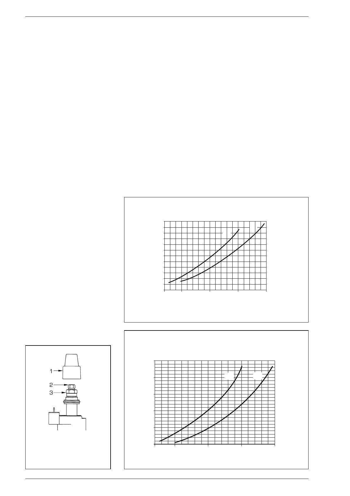
4.4 ADJUSTMENT OF HEAT
OUTPUT FOR C.H. MODE
To adjust boiler heat output for heating pur-
poses, i.e., modifying the setting made at
the factory which is approximately 16 kW
for “25” and 20 kW for “30”, use a screw-
driver to adjust the C.H. heat output trim-
mer (1 fig. 15).
To increase working pressure, turn the
trimmer clockwise; to reduce pressure,
turn the trimmer counterclockwise.
To facilitate the operations of adjusting
heat output, see the pressure/heat output
diagrams for natural gas (methane) and
butane or propane gas (figg. 21 - 21/a -
21/b).
Fig. 20/b
KEY
1 Plastic tap
2 Minimum pressure adjusting nut
3 Maximum pressure adjusting nut