2683
1
GB
INDEX
1. BURNER DESCRIPTION
One stage light oil burner.
1.1 BURNER EQUIPMENT
Flange with insulating gasket . . . .No. 1 Screws and nuts for flange to be fixed to boiler . . No. 4
Screw and nuts for flange . . . . . .No. 1 Flexible oil pipes with nipples . . . . . . . . . . . . . . . . No. 2
Grommet . . . . . . . . . . . . . . . . . . .No. 1 7 pin plug . . . . . . . . . . . . . . . . . . . . . . . . . . . . . . . No. 1
1. BURNER DESCRIPTION . . . . . . . . . . . . . 1
1.1 Burner equipment . . . . . . . . . . . . . . . . . . 1
2. TECHNICAL DATA . . . . . . . . . . . . . . . . . 2
2.1 Technical data . . . . . . . . . . . . . . . . . . . . . 2
2.2 Working fields . . . . . . . . . . . . . . . . . . . . . 2
2.3 Overall dimensions . . . . . . . . . . . . . . . . . 3
3. INSTALLATION . . . . . . . . . . . . . . . . . . . . 3
3.1 Boiler fixing . . . . . . . . . . . . . . . . . . . . . . . 3
3.2 Hydraulic systems . . . . . . . . . . . . . . . . . . 4
3.3 Electrical wiring . . . . . . . . . . . . . . . . . . . . 5
4. WORKING . . . . . . . . . . . . . . . . . . . . . . . 6
4.1 Combustion adjustment. . . . . . . . . . . . . . 6
4.2 Nozzles recommended . . . . . . . . . . . . . . 6
4.3 Electrodes setting . . . . . . . . . . . . . . . . . . 7
4.4 Air damper adjustment . . . . . . . . . . . . . . 7
4.5 Pump pressure . . . . . . . . . . . . . . . . . . . . 7
4.6 Fuel heating . . . . . . . . . . . . . . . . . . . . . . 7
4.7 Burner start-up cycle. . . . . . . . . . . . . . . . 8
5. MAINTENANCE . . . . . . . . . . . . . . . . . . . 8
6. FAULTS / SOLUTIONS . . . . . . . . . . . . . . 9
■
The burner meets protection level of IP 40, EN 60529.
■
Burner with CE marking in conformity with EEC directives: EMC 89/336/EEC, Low Voltage 73/23/EEC,
Machines 98/37/EEC and Efficiency 92/42/EEC.
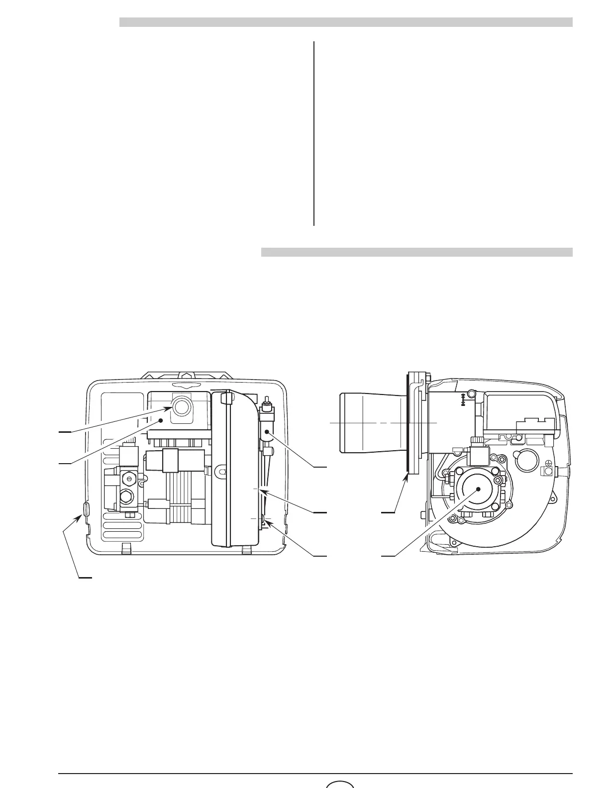
1 – Oil pump
2 – Control-box
3 – Reset button with lock-out lamp
4 – Hydraulic jack with air-damper
5 – Screws fixing air-damper
6 – Flange with insulating gasket
7 – Grommet
Fig. 1
D6272
1