Do you have a question about the Sime MERIDIAN HE 30 C and is the answer not in the manual?
Requirements for installers regarding competence, installation, and safety.
Expectations for customer interaction and service provision by installers.
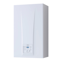
Overview of the Meridian HE 30 C boiler, its technology, and compliance.
Visual representation and measurements of the boiler's physical dimensions.
Detailed specifications and performance data of the Meridian HE 30 C boiler.
Schematic diagram illustrating the internal components and connections of the boiler.
Identification of key internal components of the boiler with numbered references.
Explanation of the boiler's anti-freeze feature and its operational conditions.
Instructions for securely mounting the boiler bracket to the wall.
Guidelines for system flushing, connection, and safety valve installation.
Procedures for correctly connecting the condensate trap for safe disposal.
Guidance on condensate disposal requirements and potential issues.
Steps for filling and pressurizing a sealed heating system for boiler operation.
Recommendations for water treatment and system flushing to prevent corrosion.
Guidelines for installing coaxial flue systems, including lengths and bends.
Instructions for installing separate exhaust and air intake ducts.
Recommended minimum spacing for flue terminals based on building context.
Requirements for connecting the boiler to the electrical supply, including safety.
Information on connecting an external temperature sensor for automatic regulation.
How to connect external wired controls like thermostats to the boiler.
Examples of boiler integration with various electronic control systems.
Detailed wiring diagram and component identification for the boiler's electrical system.
Overview of the boiler's control panel, display icons, and buttons.
Procedure for accessing and modifying installer-specific parameters and settings.
How external sensors influence boiler output temperature based on climatic curves.
Description of various functions managed by the boiler's electronic card.
Information on temperature sensors and their impact on boiler operation.
Details on the electronic system controlling ignition and flame detection.
Graph showing the pump's residual head capacity at different flow rates.
Function of the water pressure switch and how to rectify low pressure issues.
Identification and function of the gas valve component.
Steps for converting the boiler between natural gas and LPG.
Instructions for safely removing the boiler's outer casing for maintenance.
General guidelines for regular servicing to ensure efficiency and warranty compliance.
Procedure for activating and using the chimney sweep function for testing.
Description of boiler error codes, alarms, and troubleshooting steps.
Procedures for commissioning and routine servicing by a qualified engineer.
Requirements and steps for annual boiler servicing to maintain safety and performance.
Steps to verify electrical earth continuity in the appliance.
Procedure to test for short circuits in the electrical system.
Method to check the electrical polarity of the appliance.
Test to measure resistance to earth for electrical safety.
Step-by-step guide for removing the burner assembly.
Instructions for safely removing the fan unit from the boiler.
Procedure for removing and replacing the central heating thermistor.
Steps to remove and replace the domestic hot water thermistor.
Guide for replacing the safety thermostat component.
Instructions for replacing the exhaust temperature sensor.
Procedure for removing and replacing the ignition electrode.
Steps for removing and replacing the ionisation electrode.
Procedure for removing and replacing the gas valve.
Instructions for removing and replacing the main heat exchanger.
Steps for removing and replacing the pump.
Guide for removing and replacing the domestic hot water heat exchanger.
Guide for removing and replacing the expansion vessel.
Context on condensate pipe freezing issues and their causes.
Updated recommendations for installing condensate drainage pipes to prevent freezing.
Guidance on terminating condensate pipes internally into waste systems.
Procedures for using a condensate pump for internal discharge.
Measures for external condensate pipe runs to prevent freezing.