41
EN
55
55
65
65
65
65
=
=
124
350
L
K
165
124
60/100
118700
65
22
718
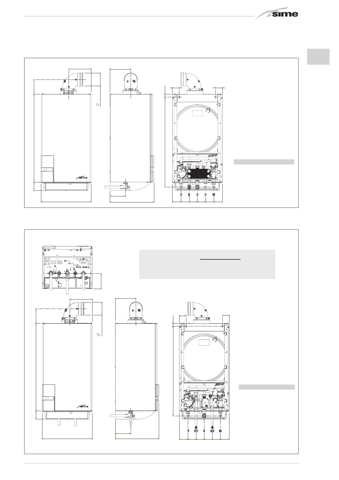
Fig. 1/b
1.2.3 “20 - 25 BFT” models (fig. 1/b)
65
65 65
65
=
=
55
55
350
12 5
L
165
K
700
65
118
22
60/100
718
Fig. 1/a
1.2.2 “25 - 30 - 35 BF” models (fig. 1/a)
CONNECTIONS
R C.H. return
G 3/4” (UNI-ISO 228/1)
M C.H. flow
G 3/4” (UNI-ISO 228/1)
G Gas connection
G 3/4” (UNI-ISO 228/1)
E D.H.W. inlet
G 1/2” (UNI-ISO 228/1)
U D.H.W. outlet
G 1/2” (UNI-ISO 228/1)
DIMENSIONS
25 30 35
L mm 400 450 450
K mm 180 205 205
ATTENTION: The “BFT” version is designed for the connection of a re-
mote boiler, to use it as a boiler ONLY FOR HEATING it is necessary:
- to disconnect the D.H.W. sensor (SB)
- set the PAR 2=4.
All modules are designed to be used by qualified technical personnel.
CONNECTIONS
R C.H. return
G 3/4” (UNI-ISO 228/1)
M C.H. flow
G 3/4” (UNI-ISO 228/1)
G Gas connection
G 3/4” (UNI-ISO 228/1)
R3 D.H.W. tank return
G 3/4” (UNI-ISO 228/1)
M2 D.H.W. tank outlet
G 3/4” (UNI-ISO 228/1)
DIMENSIONS
L mm 400
K mm 180