Do you have a question about the Sime MURELLE HM and is the answer not in the manual?
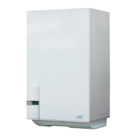
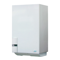
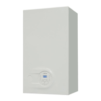
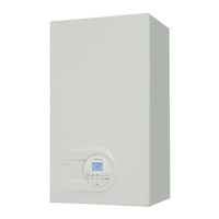
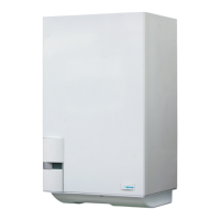
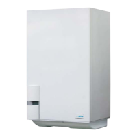
Overview of MURELLE HM premixed gas condensation thermal modules and their technology.
Detailed dimensions for Murelle HM 25 T-35 T and 25-30-35 models.
Diagram and specifications for Murelle HM 25 T-35 T dimensions.
Diagram and specifications for Murelle HM 25-30-35 dimensions.
Comprehensive technical specifications for Murelle HM boilers, including outputs and efficiencies.
Detailed functional diagrams for MURELLE HM 25-30-35 and 25 T-35 T models.
Identification and description of the main internal components of the MURELLE HM boiler.
General guidelines and requirements for boiler installation in various environments.
Instructions for installing multiple MURELLE HM boilers in sequence or cascade.
Configuration and operation of the boiler in MODBUS communication mode.
Setting up boilers for combined cascade and MODBUS communication.
Connecting the RS-485 board to optional INSOL or ZONA MIX kits.
Detailed breakdown of the boiler's control panel, icons, and buttons.
How to access and interpret installer information displayed on the boiler.
Guide to installer parameters including fast configuration and D.H.W./heating settings.
Covers external sensor, card functions, temperature sensors, and electronic ignition.
Graph of residual head for heating system vs. flow rate.
Information on the boiler's gas valve and its components.
Procedure for converting the boiler between natural gas and LPG.
Instructions for safely removing the boiler shell for maintenance access.
Routine maintenance tasks including filter cleaning, floor drying, and pump checks.
Comprehensive guide to boiler anomalies, error codes, and troubleshooting.
