84
The boiler must be installed in a fixed loca-
tion and only by specialized and qualified
firms in compliance with all instructions
contained in this manual. Furthermore, the
installation must be in accordance with cur-
rent standards and regulations.
2.1 INSTALLATION
– Boilers can be installed in all domestic envi-
ronments without any whatsoever limit in
terms of location and comburent air supply.
–
These boilers can also be installed in par-
tially covered areas, as per EN 297, with a
maximum ambient temperature of 60°C
and a minimum ambient temperature of -
5°C. It is generally advisable to install the
boilers below weathered roofs, on the bal-
cony or in a protected niche, to protect
them from exposure to weathering agents
(rain, hail and snow). All boilers provide a
standard antifreeze function.
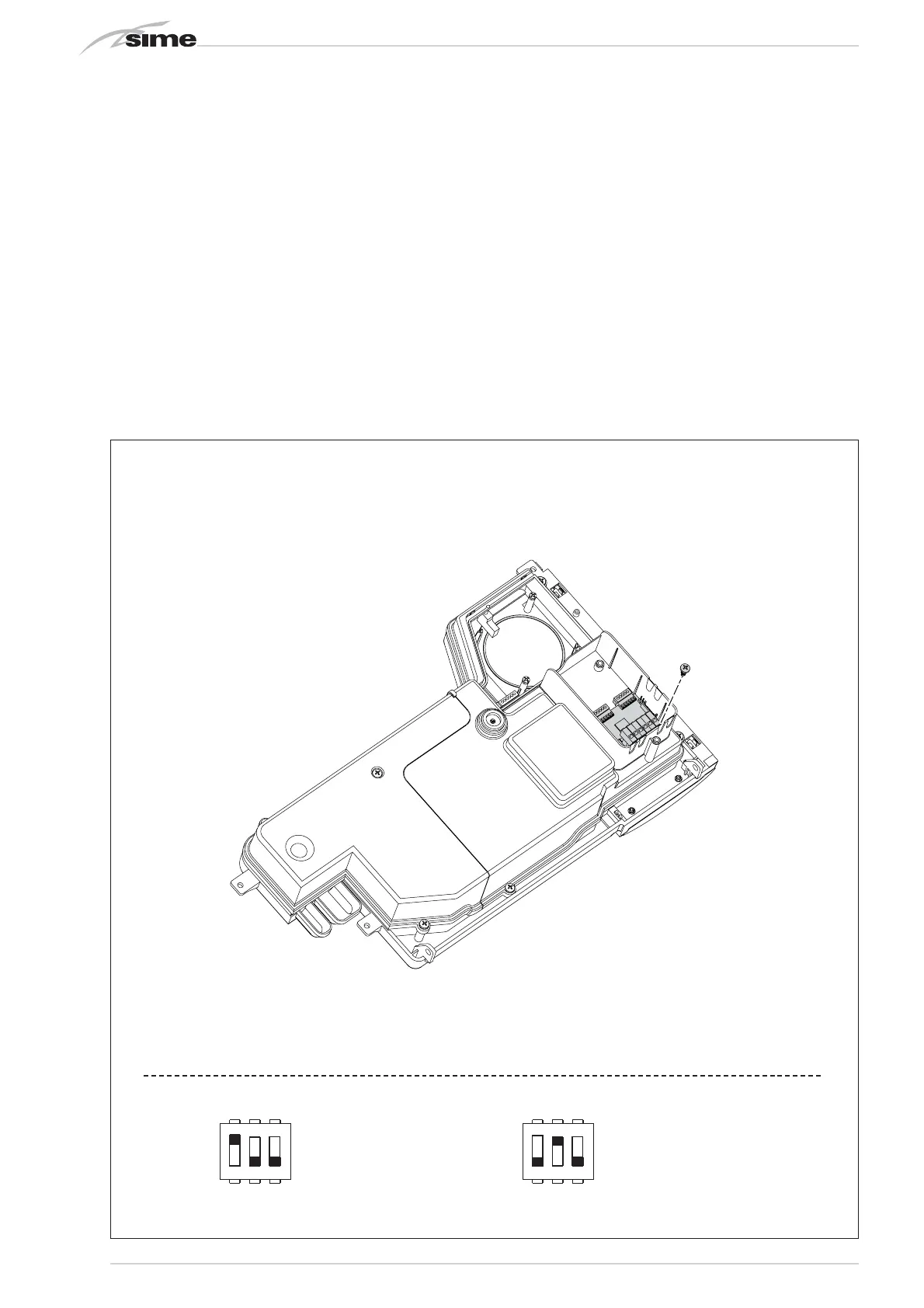
2.1.1 Sequence/cascade installation of
MURELLE HM 25 T - 35 T boilers
(fig. 4/a)
In the event of sequence/cascade installa-
tion, you must request an RS-485 kit for
every single boiler of the main unit to mana-
ge up to 8 boilers in the cascade code
8092243.
ATTENTION: In sequence/cascade instal-
lations, it is mandatory to arrange the
thermal system with the hydraulic sepa-
rator and safety devices.
The board must be located on the rear of
the control panel, as indicated in figure
4/a. Set the required operating mode
(CASCADE or MODBUS) by selecting the
DIP SWITCH of the board as indicated in
figure 4/a.
CASCADE mode (fig. 4/b)
Electrically connect all the boilers that form
the modular cascade thermal system and
set installer parameters PAR 15 on every
single boiler as indicated in fig. 4/b.
2 INSTALLATION