105
ES
PT
ENG
3.3 ACCESS TO
INSTALLER'S
PARAMETERS
For access to the installer's parameters,
press simultaneously the keys and
or 2 seconds (3 fig. 12).
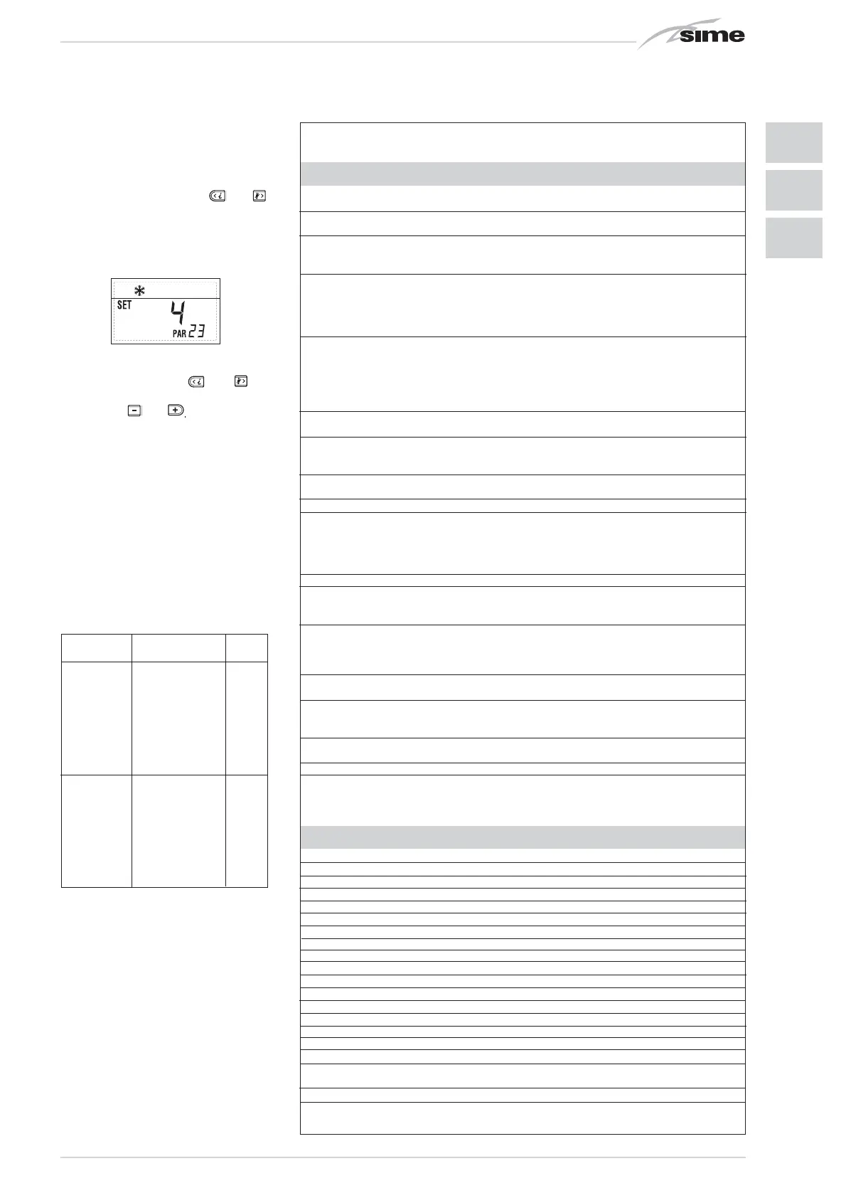
For example, the parameter PAR 23 is
visualised on the display of the control
panel in the following way:
The parameters scroll forwards and
backwards with the key and and
the default parameters can be changed
with the keys and .
The standard visualisation returns automa-
tically after 60 seconds, or by pressing one
of the control keys (2 fig. 12) excluded the
key RESET.
3.3.1 Replacing the board or
RESETTING parameters
If the electronic board is replaced or reset,
it is necessary to configure PAR 1 and PAR
2 by associating the following values to
each type of boiler to be able to restart the
boiler:
PARAMETERS INSTALLER
FAST CONFIGURATION
PAR DESCRIPTION RANGE UNIT OF INC/DEC DEFAULT
MEASUREMENT UNIT SETTING
1 Combustion configuration -- = ND = = “- -”
1 ... 31
2 Hydraulic configuration -- = ND = = “- -”
1 ... 14
3 Timetable 2 programmer 1 =
DHW + Recirc. pump
==1
2 = DHW
3 = Recirculation pump
4 Pressure transducer disabler 0 = Disabled = = 1
1 = Enabled 0-4 BAR
2 = Enabled 0-6 BAR
3 = Enabled 0-4 BAR (NO ALL 09)
4 = Enabled 0-6 BAR (NO ALL 09)
5 Assignment of auxiliary relay AUX 1 = Remote supply = = 1
2 = Recirculation pump
3 = Automatic load.
4 = Remote alarm NC
5 = Heat pump
6 = Zone 2 valve
6 Luminous bar indicating presence 0 = Disabled = = 1
of voltage 1 = Enabled
7 Allocation of CR73 channels 0 = Not assigned = = 1
1 = Circuit 1
2 = Three-zone circuit
8 Fan rpm Step ignition 0,0 ... 81
rpmx100 0,1 from 0,1 to 19,9 0,0
1 from 20 to 81
9 Long chimneys 0 ... 20 % 1 0
10 Remote control option setting 1 = CR 73 = = 1
2 = CR 53
3 = RVS 43.143
4 = RVS 46.530
5 = RVS 61.843
11 Correction values external sensor -5 ... +5 °C 1 0
12 Backlighting duration -- = Always sec. x 10 1 3
0 = Never
1 ... 199
13 Modulating pump speed -- = None % 10 --
AU = Automatic mod.
30...100 = % Settable
modulation
14 Setting second input TA -- = Contact TA -- -- --
5...160 = Input 0...10VDC
15 Cascade address -- = Not enabled -- 1 --
0 = Master
1...7 = Slaves
16 ModBus address -- = Not enabled -- 1 --
1...31 = Slaves
17 ModBus communication configuration 1 ... 30 -- 1 25
19 Type circuit 0 = Two zones -- -- 0
1 = Three zones
D.H.W. - HEATING
PAR DESCRIPTION RANGE UNIT OF INC/DEC DEFAULT
MEASUREMENT UNIT SETTING
20 Minimum heating temperature Zone 1 PAR 64 OEM ... PAR 21 °C 1 20
21 Maximum heating temperature Zone 1 PAR 20 ... PAR 65 OEM °C 1 80
22 Heating curve slope Zone 1 3 ... 40 -- 1 20
23 Minimum heating temperature Zone 2 PAR 64 OEM ... PAR 24 °C 1 20
24 Maximum heating temperature Zone 2 PAR 23 ... PAR 65 OEM °C 1 80
25 Heating curve slope Zone 2 3 ... 40 -- 1 20
26 Minimum heating temperature Zone 3 PAR 64 OEM ... PAR 27 °C 1 20
27 Maximum heating temperature Zone 3 PAR 26 ... PAR 65 OEM °C 1 80
28 Heating curve slope Zone 3 3 ... 40 -- 1 20
29 ∆t heating circuit 10 ... 40 °C 1 20
30 Post-circulation heating time 0 ... 199 Sec. 10 30
31 Maximum heating capacity 30 ... 100 % 1 100
32 Zone 1 pump activation delay 0 ... 199 10 sec. 1 1
33 Start-up delay 0 ... 10 Min. 1 3
34 Additional source activation threshold -- , -10 ... 40 °C 1 “- -”
35 Boiler antifreeze 0 ... +20 °C 1 3
36 External sensor antifreeze -5 ... +5 °C 1 -2
37 Band saturation -- =
Disabled
%1100
flowmeter modulation 0 ... 100
38 D.H.W. post-circulation time 0 ... 199 Sec. 1 0
39 Anti-legionella 0 =
Disabled
-- -- 0
(only D.H.W tank)) 1 =
Enabled
GAS MODELS PAR 1
25 - 25 T 1
METHANE 30 2
(G 20) 35 - 35 T 3
25 - 25 T 9
PROPANE 30 10
(G 31) 35 - 35 T 11
 Loading...


