43
EN
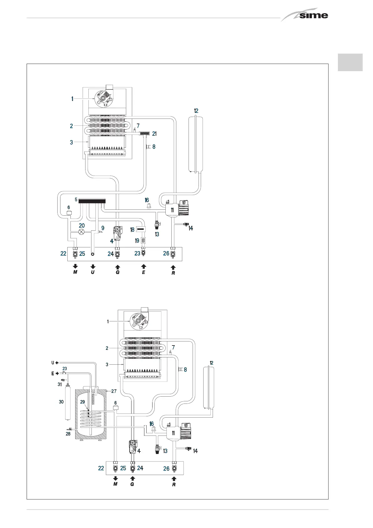
1.4 FUNCTIONAL DIAGRAM (fig. 2)
Fig. 2
“25-30 OF/25-30-35 BF” models
“20-25 BFT” models
KEY
1 Fan (BF - BFT model)
2 Primary exchanger
3 Combustion chamber
4 Gas valve
5 D.H.W. exchanger with plates
6 Deviator valve
7 C.H. sensor (SM)
8 Safety thermostat
9 D.H.W. sensor (SS)
11 Circulator with air release vent
12 Expansion vessel
13 3 BAR safety valve
14 Boiler discharge
16 Water pressure transducer
18 D.H.W. flowmeter
19 D.H.W. filter
20 Loading
21 Aqua Guard Filter System
22 Connection plate (optional)
23 D.H.W. cock (optional)
24 Gas cock (optional)
25 C.H. flow cock (optional)
26 C.H. return cock (optional)
27 D.H.W. storage tank BT 100 (optional)
28 Boiler discharge (optional)
29 D.H.W. sensor (SB)
30 D.H.W. expansion vessel 4 litre (optional)
31 D.H.W. safety valve 7 BAR (optional)
CONNECTIONS
U D.H.W. outlet
E D.H.W. inlet
G Gas connection
M C.H. flow
R C.H. return