45
EN
The boiler must be installed in a fixed loca-
tion and only by specialized and qualified
firms in compliance with all instructions
contained in this manual. Furthermore, the
installation must be in accordance with cur-
rent standards and regulations.
2.1 INSTALLATION
-
In the rooms where “Type B” boilers
are installed, the air required for correct
combustion of the gas consumed by the
appliance must be able to flow in. It is
therefore necessary to make openings
that cannot be blocked in the outer walls,
which must be at least 6 cm
2
for every
kW of thermal capacity installed and with,
in any case, a minimum of 100 cm
2
.
- “Type C” appliances, with combustion
chamber and air supply sealed off from
the environment, can be installed in any
room in the house.
- “Type B and C” boilers are suitable for
functioning in a partially protected place,
as according to EN 297, with maximum
environmental temperature of 60°C and
minimum of -5°C. We recommend installa-
tion of these boilers under the protruding
slope of a roof, on a balcony, or in a pro-
tected niche, always providing they are not
directly exposed to adverse weather (rain,
hail, snow). The boilers are provided alre-
ady equipped with anti-freeze functions.
2.1.1 Anti-freeze function
The boilers are equipped with anti-freeze
function which activates the pumps and the
burner when the temperature of the water
contained inside the appliance drops to
below 6°C. The anti-freeze function is ensu-
red, however, only if:
- the boiler is correctly connected to the
gas and electricity supply circuits;
- the boiler is constantly fed;
- the boiler ignition is not blocked;
- the essential components of the
boiler are all in working order
In these conditions the boiler is protected
against frost down to an environmental
temperature of -5°C.
ATTENTION: In the case of installation in a
place where the temperature drops below
0°C, the connection pipes must be protected.
2.2 COMPLEMENTARY ACCESSORIES
To facilitate connecting the boiler to the
system, the following accessories can be
supplied on request, complete with instruc-
tions for assembly:
- Installation plate code 8075438.
- Curvette and gas taps/sanitary water
output set code 8075418.
- Taps kit code 8091806.
- Taps kit boiler BFT code 8091820.
- Hydraulic connection kit boiler BFT/
BT100 tank unit code 8091113.
- Kit of couplings for replacing wall-hung
boilers of other makes code 8093900.
- Solar kit INSOL only for heating boilers
code 8092235.
- Solar kit for the instantaneous boilers
code 8105101 in coupling to kit INSOL.
- Mixed area kit ZONA MIX code 8092234.
- Antifreeze heaters kit -15°C code
8089806 (BF-BFT models).
2.3 CONNECTING UP SYSTEM
To protect the heat system from damaging
corrosion, incrustation or deposits, before
installation it is extremely important to clean
the system using suitable products such as,
for example,
Sentinel X300 (new systems),
X400 and X800 (old systems) or Fernox
Cleaner F3
. Complete instructions are pro-
vided with the products but, for further infor-
mation, you may directly contact
SENTINEL
PERFORMANCE SOLUTIONS LTD or FERNOX
COOKSON ELECTRONICS
. For long-term pro-
tection agains corrosion and deposits, the
use of inhibitors such as
Sentinel X100 or
Fernox Protector F1
is recommended after
cleaning the system. It is important to check
the concentration of the inhibitor after each
system modification and during maintenan-
ce following the manufacturer’s instructions
(specific tests are available at your dealer).
The safety valve drain must be connected to
a collection funnel to collect any discharge
during interventions. If the heating system is
on a higher floor than the boiler, install the
on/off taps supplied in kit optional on the
heating system delivery/return pipes.
WARNING: Failure to clean the heat
system or add an adequate inhibitor inva-
lidates the device’s warranty.
Gas connections must be made in accor-
dance with current standards and regula-
tions. When dimensioning gas pipes from
the meter to the module, both capacity volu-
me (consumption) in m
3
/h and gas density
must be taken into account.
The sections of the piping making up the
system must be such as to guarantee a
supply of gas sufficient to cover the maxi-
mum demand, limiting pressure loss betwe-
en the gas meter and any apparatus being
used to not greater than:
– 1.0 mbar for family II gases (natural gas);
– 2.0 mbar for family III gases (butane or
propane).
An adhesive data plate is sticked inside the
front panel; it contains all the technical data
identifying the boiler and the type of gas for
which the boiler is arranged.
2.3.1 Filter on the gas pipe
The gas valve is supplied ex factory with an
inlet filter, which, however, is not adequate
to entrap all the impurities in the gas or in
gas main pipes. To prevent malfunctioning
of the valve, or in certain cases even to cut
out the safety device with which the valve is
equipped, install an adequate filter on the
gas pipe.
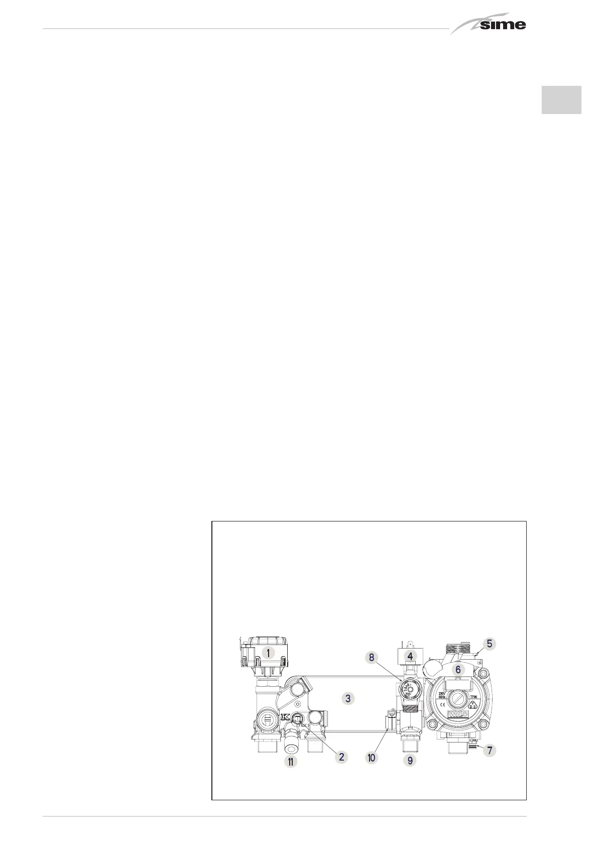
2.5 SYSTEM FILLING (fig. 4)
Filling of the boiler and the system is done by
the system filling (11). The charge pressure,
2 INSTALLATION
Fig. 4
45
KEY
1 Diverter valve (VD)
2 D.H.W. sensor (SS)
3 D.H.W. exchanger with plates
4 Water pressure transducer (TPA)
5 Air release vent
6 Circulator (PI)
7 Boiler discharge
8 3 BAR safety valve
9 D.H.W. filter
10 D.H.W. flowmeter sensor
11 System loading

 Loading...


