59
EN
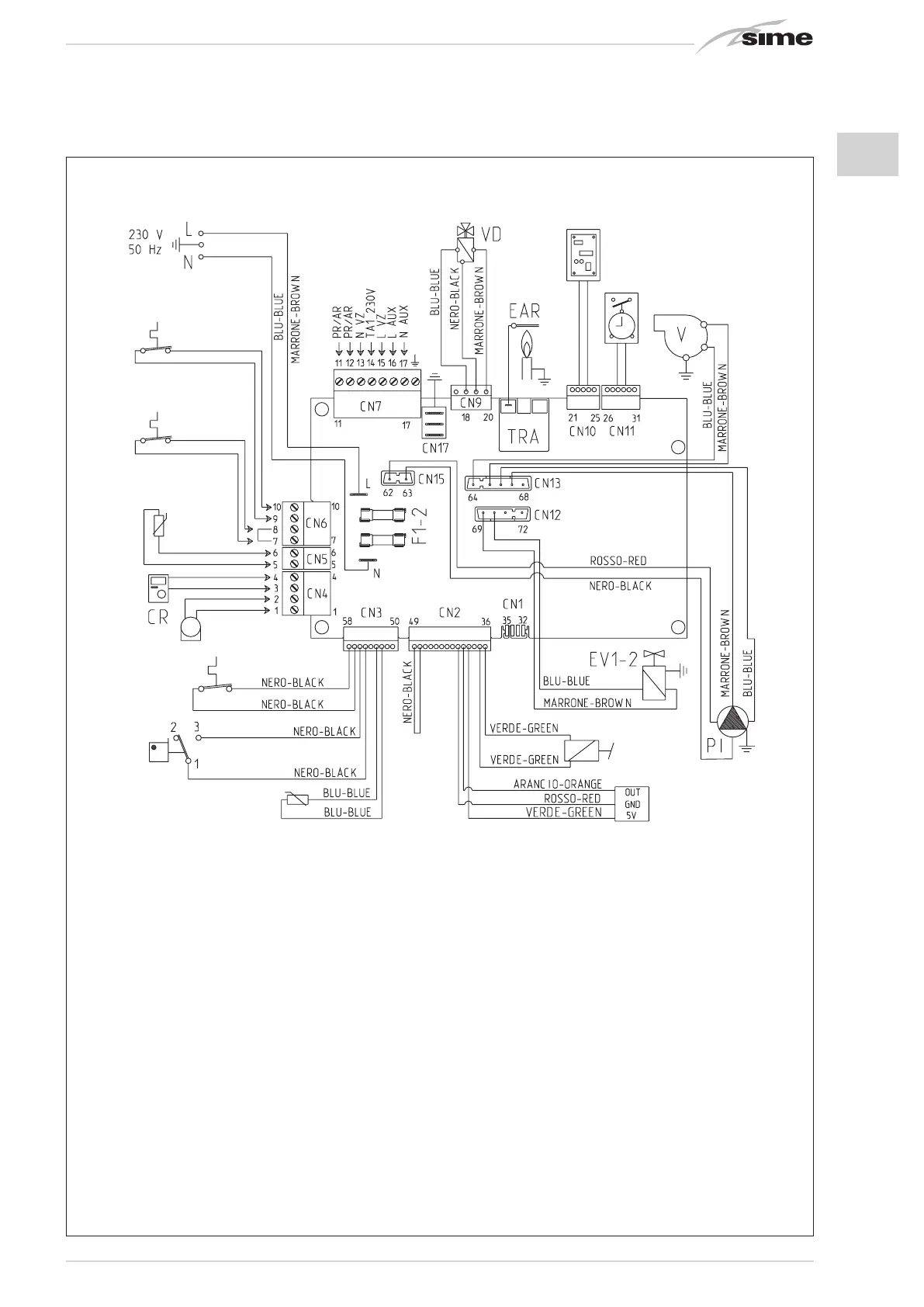
TPA (5 VDC)
M (17 VDC)
SM (5 VDC)
PF (24 VRAC)
TS (24 VRAC)
SE (5 VDC)
SB (5 VDC)
TA1 (24 VRAC)
TA2 (24 VRAC)
EXP (24 VRAC)
OP (24 VAC)
Cod. 6301407D
Fig. 13/b
KEY
F1-2 Fuse (4 AT)
TRA Ignition transformer
Pl System pump
V Fan
EAR Ignition/detection electrode
EV1-2 Gas valve coil
TS Safety thermostat
PF Fumes thermostat
M Modulator
SM Heating sensor
VD Deviator valve
TPA Pressure transducer
TA 1 Zone 1 environment thermostat
TA 2 Zone 2 environment thermostat
SB D.H.W. tank sensor
CR Remote control SIME HOME (optional)
SE External sensor (optional)
OP Programming clock (optional)
EXP Expansion card
PR/AR Recirculation pump control
or remote alarm
VZ Zone valve
AUX Auxiliary connection
NOTE: Connect TA1 to the clamps 7-8 after having
removed the bridge.
CONNECTOR SPARE PART CODES:
CN2 code 6316288
CN3 code 6299993
CN5 code 6316200
CN6 code 6316202
CN9 code 6316295
CN12 code 6299991
CN13/15 code 6316279 (“20 BFT”)
CN13/15 code 6316272 (“25 BFT”)
2.12.3 Murelle EV 20 - 25 BFT (fig. 13/b)