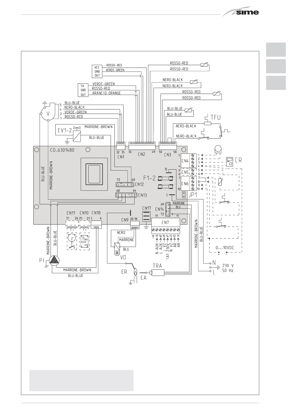
Fig. 11/a
KEY
F1-2 Fuse (4 AT)
TRA Ignition transformer
PI System pump
VFan
TL Limit thermostat
EA Ignition electrode
ER Detection electrode
EV1-2 Gas valve coil
TS Safety thermostat
SF Sensor fumes
TFU Thermal fuse
VD Diverter valve
SM C.H. flow sensor
SR C.H. return sensor
SS D.H.W. sensor
TPA Pressure transducer
FLM D.H.W. flowmeter
TA1 Zone 1 environment thermostat
JP1 Selection TA2 or 0-10 VDC
TA2 Zone 2 environment thermostat
ST Solar heat sensor
CR Remote control CR73 (optional)
SE External sensor (supplied with)
OP Programming clock (optional)
EXP Expansion card
AR Remote alarm
VZ Zone valve
AUX Auxiliary connection
NOTE: Connect TA1 to the clamps 7-8
after having removed the bridge.
CONNECTOR SPARE PART CODES:
CN1/13 code 6319146
CN2 code 6319148
CN3 code 6319145
CN4 code 6316203
CN6 code 6316202
CN7 code 6316204
CN9 code 6316274
CN12 code 6316280
CN14 code 6316213
CN18 code 6319147
For the range 0 ... 10VDC:
- Remove the jumper JP1
- Connect the positive signal at terminal 10 of CN6
- Connect the negative signal at terminal 4 of the CN4.