GR
RO
RUS
SCG
IT
ES
PT
GB
45
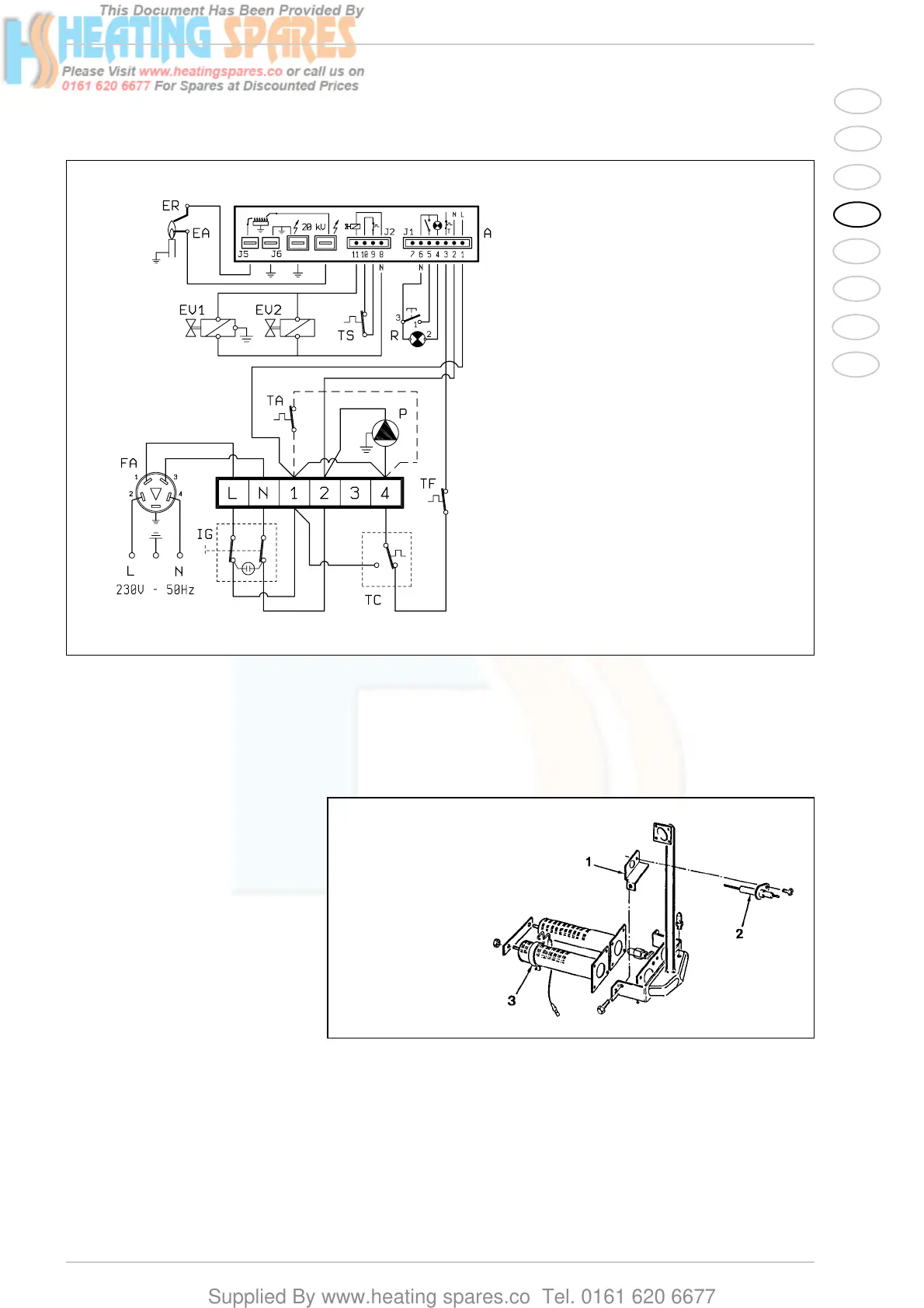
KEY
A FM 11 programmer
IG Main switch
TC Boiler stat
EA Ignition electrode
ER Ionisation electrode
P Circulating pump
TS Safety stat
EV1 Modulating coil
EV2 Modulating coil
TF Smoke stat
R Lock out lamp
TA Room stat
FA EMC filter
NOTE: When a room stat is to be fitted
remove the link between terminal 1
and 4 on the connector plug.
2.6.1 Wiring diagram
Fig. 4
3.1 ELECTRONIC IGNITION
The boilers are equipped with electro-
nic ignition without pilot flame; they are
therefore equipped with an electric
control and protection device. An elec-
tronic programmer, model Brahma FM
11, controls the ignition and the ionisa-
tion by means of two electrodes as
shown in fig. 5.
Maximum safety is garanteed because
in case of accidental extinction of the
burner the gas flow is stopped within 1
second. A reference mark made on
the burner ensures the proper applica-
tion of the ignition electrode.
3.1.1 Working cycle
Before lighting the boiler check with a
voltmeter that the electric connection
to the terminal board has been pro-
perly made observing the phase and
neutral positions of the wiring diagram.
Press the main switch on the control
board; the lamp will light if there is
power. At this stage the boiler will start
to work sending, via the FM 11 pro-
grammer, a discharge current to the
electrode and, at the same time, ope-
ning the gas valve. Normally the burner
takes 1 or 2 seconds to light.
It may however fail to light, in which
case the boiler lock-out lamp will be
activated. The main causes maybe:
– No gas supply
The equipment performs regularly
sending voltage to the ignition elec-
trode that continues to spark for max.
10 seconds, without detecting the
burner starting, then it shuts down.
It may occur at the first starting or
when the boiler has not been used
for a long period of time and there is
3 CHARACTERISTICS
KEY
1 Ionisation electrode support
2 Ionisation electrode
3 Ignition electrode
Fig. 5



 To Next Page