Assembly / Installation 4
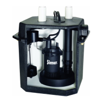
Step 6 (See Figure 5)
• Align the cover with the discharge pipe and cords.
• Pull the cords through the non-threaded hole in the
basin cover.
• Place the cover over the discharge pipe.
NOTE: Be sure that you have put one of the square-cut
O-Rings in the discharge port in the cover. The discharge
pipe should seat against it to hold it there.
• Install the cords in the cord grommet
• Install the cord/grommet assembly in the non-threaded
hole in the basin cover; don’t pull the cords tight.
Step 7 (See Figure 5)
Fasten the basin cover to the basin with the capscrews
previously inserted in the cover (Step 5).
IMPORTANT: To prevent leaks, be sure the locating cleats
on the corners of the basin gasket are outside the edges of
the basin rim, not pressing against the rim.
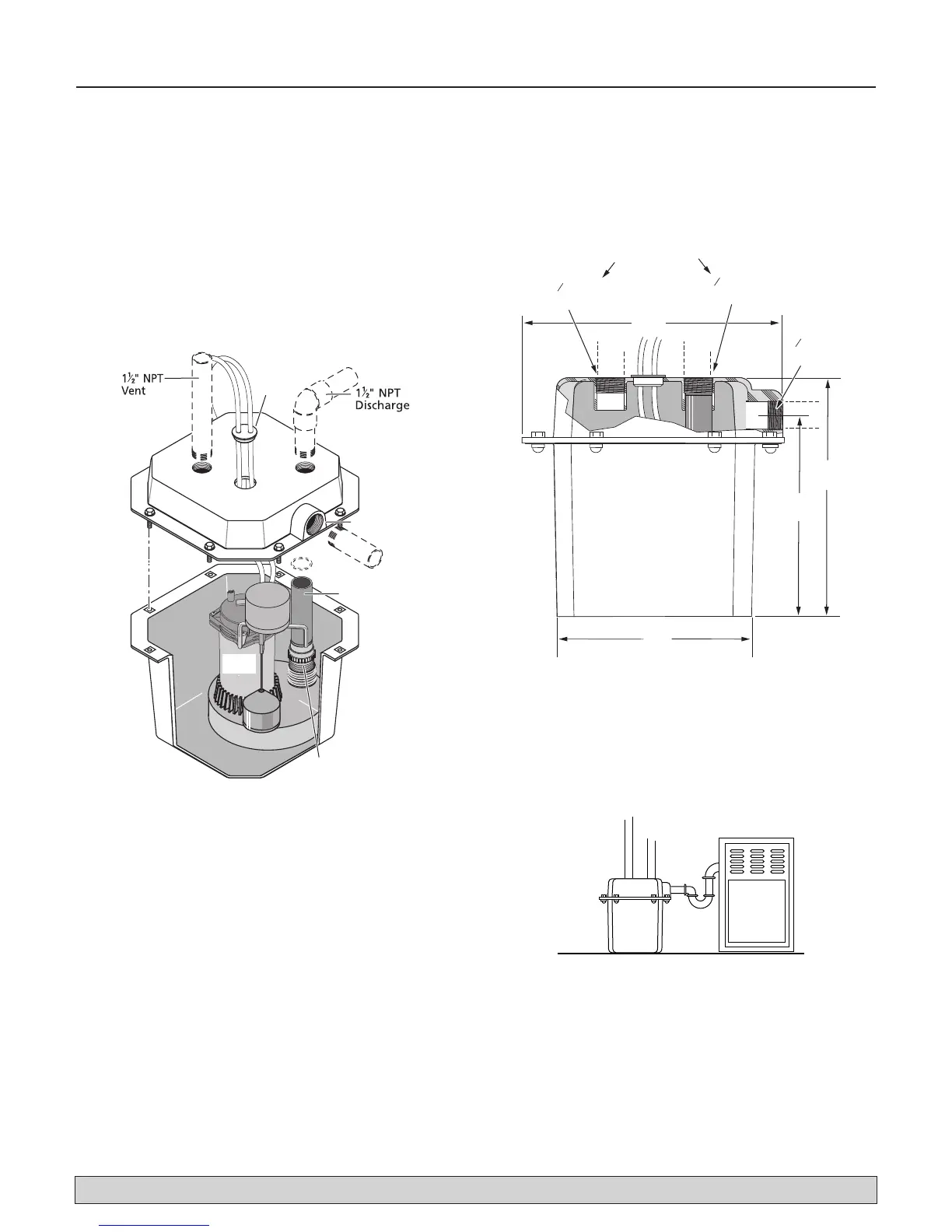
INSTALLATION (See Figure 6)
The basin (system) should be located at the lowest place
possible relative to the area to be drained.
NOTE: Make sure that the inlet of the pre-plumbed system
is lower than the water to be pumped.
1. Install inlet pipe in opening as shown. Use RTV sealants
or Plasto-Joint Stik* to seal threads. See Figures 7, 8, and
9, page 4 and 5, for typical installation arrangements.
*Lake Chemical Co., Chicago, Illinois
don't go past end of threads.