SRP9170/80 P25 Portable Radio – User Manual
© ComGroup Australia 2010 Page 16 TNM-U-E-0091 1.4a
C
Connecting icon. Shown when a text message is being sent and the
connection is in progress.
!
Connection Fail icon. Shown when a text message transmission has
failed.
*
Radio has stopped on a scan channel.
4.2 M
ENUS
The menu structure on the SRP9180 is configurable using the Field Programmer. A system
administrator usually tailors the order and presence of the menu options to specific customer
requirements.
This section will describe all the possible menus.
Normally the menus are divided into two menu lists.
These are normally the Main menu list and the Setup menu list. Menu selections that are
not frequently accessed are normally put under the Setup menu list.
In the default configuration, the Main menu contains the Zone screen and a Setup screen.
This allows access to the second “Setup” menu level.
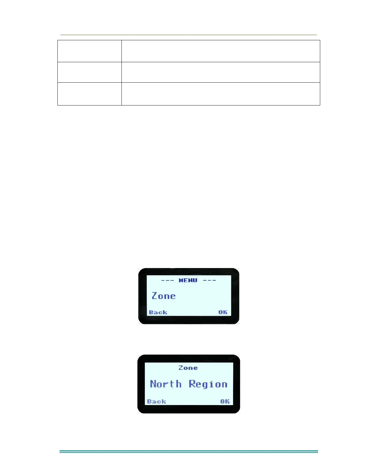
4.2.1 Zone
The Zone Screen is used for changing Zones. A Zone is normally defined as a group of radio
channels with a common operational role.
When the “Zone” menu option is displayed, press the “OK” key to enter the “Zone“ select
screen.