DRAFT D
TNM-M-E-0001 Page 16
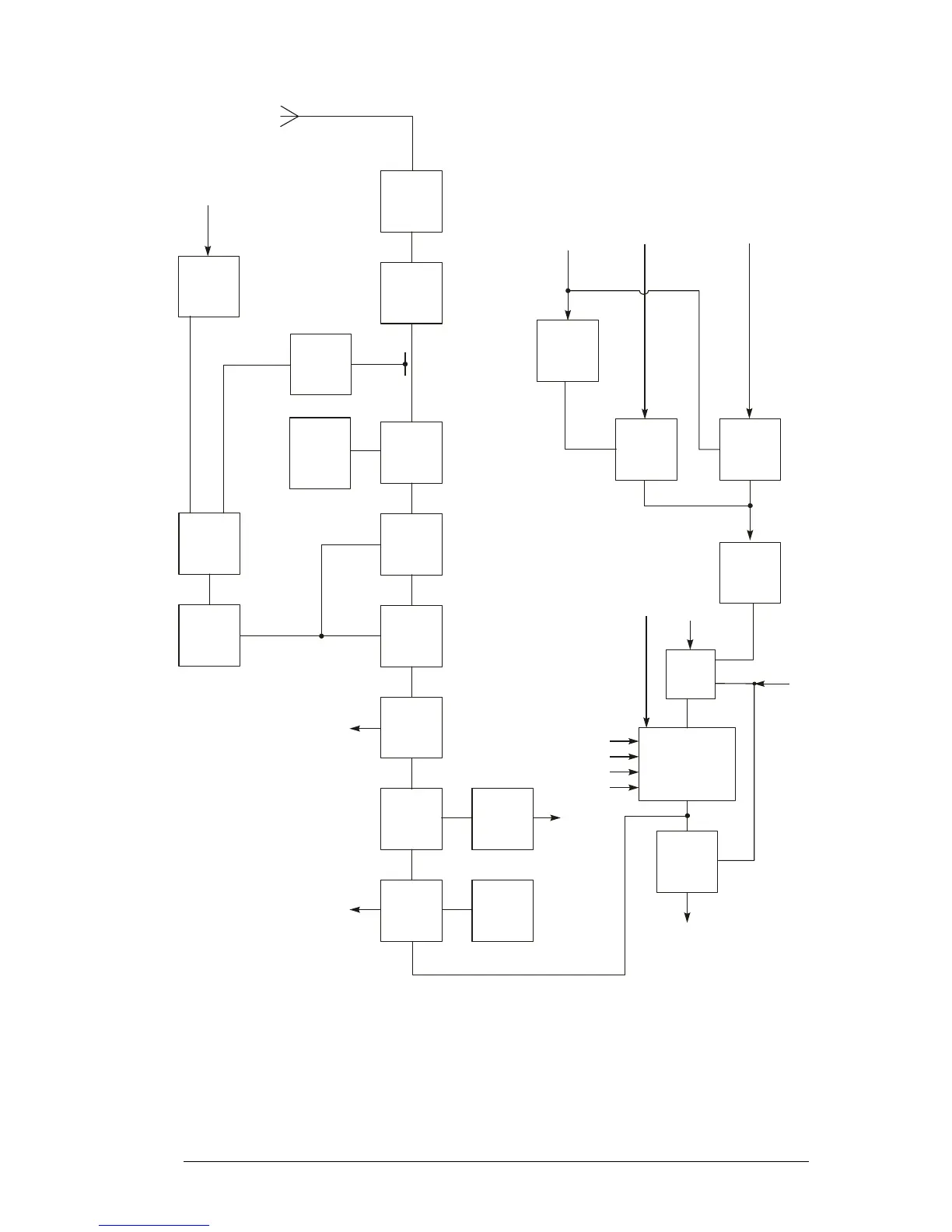
Figure 3-2 VHF/UHF Transmitter Block Diagram
An active filter comprising Q14, 17,18 and 19 provides isolation to minimise power supply noise
at the PA. This is achieved by maintaining a voltage differential of approximately 1V across Q14
and indirectly filtering its gate voltage. Q14 is switched on only during transmit via R523 to
minimise receiver power requirements.
9
0
0
0
_
1
7
T
x
/
R
x
S
w
i
t
c
h
D
6
1
0
/
6
1
1
T
x
V
C
O
Q
6
0
2
T
x
V
C
O
S
w
i
t
c
h
Q
6
0
3
T
x
B
u
f
f
e
r
/
A
m
p
Q
6
0
6
/
6
0
9
/
6
1
2
P
o
w
e
r
C
o
n
t
r
o
l
Q
3
/
1
0
V
C
O
B
u
f
f
e
r
Q
6
0
4
/
6
0
5
S
y
n
t
h
e
s
i
s
e
r
B
u
f
f
e
r
Q
6
0
7
T
x
P
A
D
r
i
v
e
r
Q
1
2
C
o
m
p
a
r
a
t
o
r
U
3
A
Q
1
5
/
1
6
T
X
P
A
U
2
T
x
P
A
F
i
l
t
e
r
/
S
w
i
t
c
h
Q
1
4
/
1
7
/
1
8
/
1
9
P
o
w
e
r
C
o
n
t
r
o
l
D
e
t
e
c
t
o
r
D
6
B
u
f
f
e
r
U
3
B
A
n
t
e
n
n
a
S
w
i
t
c
h
D
3
/
4
/
5
A
n
t
e
n
n
a
F
i
l
t
e
r
L
1
0
/
1
1
/
1
2
R
x
A
F
S
w
i
t
c
h
U
1
0
3
C
A
D
C
/
D
A
C
C
O
D
E
C
U
8
0
0
F
r
o
m
F
P
G
A
/
D
S
P
R
x
A
F
T
X
M
O
D
1
V
C
O
C
o
n
t
r
o
l
V
o
l
t
s
C
P
P
T
o
R
x
M
i
x
e
r
L
O
1
R
x
t
o
U
7
0
1
R
x
/
T
x
A
F
S
w
i
t
c
h
U
1
0
3
B
M
i
c
A
m
p
Q
8
1
2
F
r
o
m
I
Q
D
e
m
o
d
u
l
a
t
o
r
U
4
0
1
Q
I
M
O
D
1
O
N
(
T
x
/
R
x
A
F
C
o
n
t
r
o
l
)
T
x
P
o
w
e
r
S
e
t
F
r
o
m
M
u
l
t
i
p
l
e
x
e
r
U
9
0
2
G
a
t
e
T
x
M
i
c
A
u
d
i
o
T
x
O
p
t
i
o
n
s
A
u
d
i
o
+
D
a
t
a
A
U
D
I
N
2
A
U
D
I
N
1
F
r
o
m
F
P
G
A
S
Y
N
T
H
G
a
t
e
U
1
0
7
G
a
t
e
U
1
0
8
I
n
v
e
r
t
e
r
Q
2
0