Environmental Specifications
• Operating temperature: 32 °F to 120 °F (0 °C to 49 °C)
• Humidity: up to 93% relative humidity at 90 °F (32 °C)
Setting Jumpers
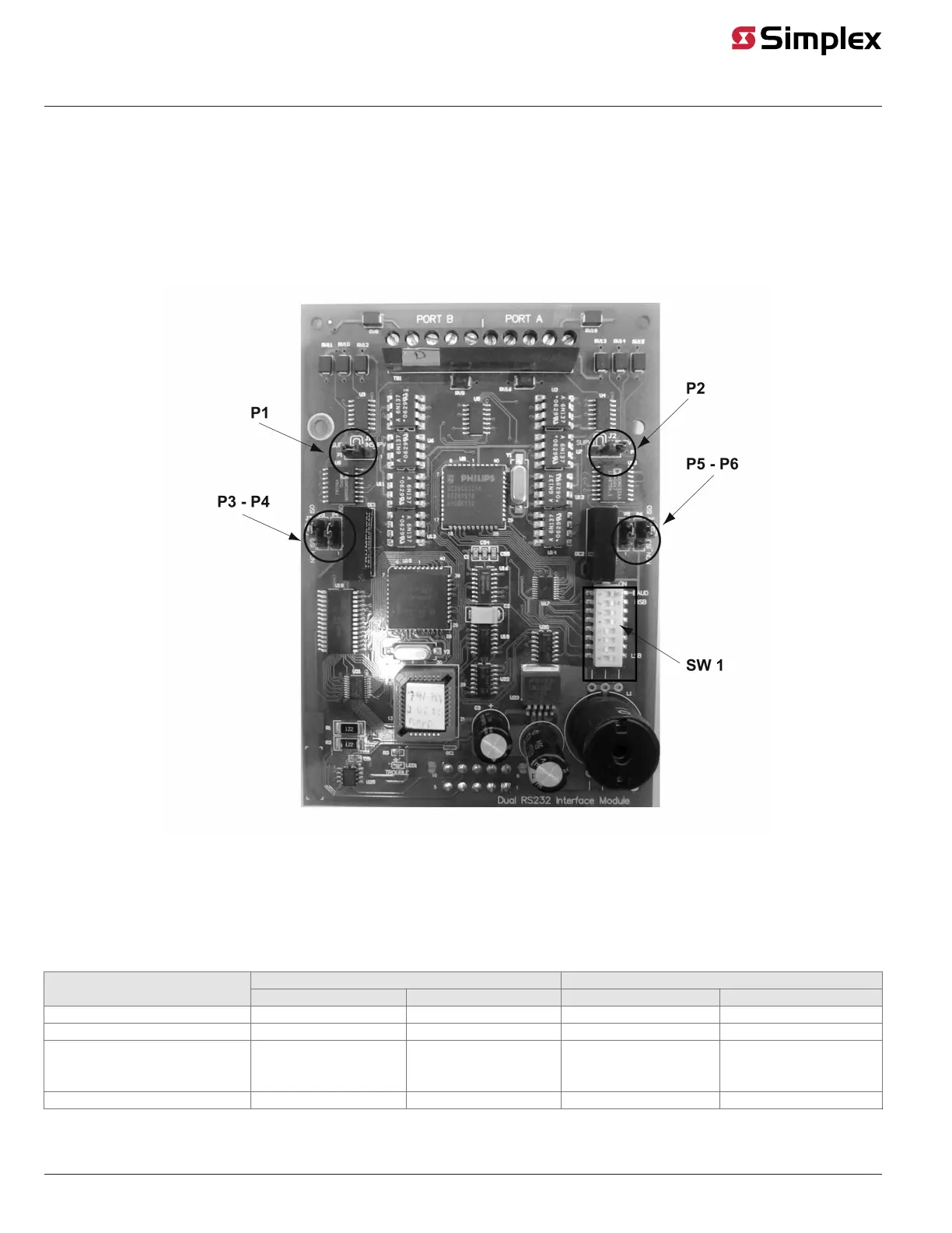
Jumper Locations
Figure 1 shows the locations of the jumpers on the dual RS-232 interface module, and identifies the number assigned to each jumper pin. The specific
jumper settings required on the dual RS-232 interface module depend on the type of device being attached to the card. Refer to Table 1 for specific
jumper configurations.
Figure 1: Location of Jumpers
Jumper Settings for Specific Devices
Table 1 lists the jumper settings for the range of devices that can be attached to the dual RS-232 interface module.
Refer to Figure 1 for the locations of the jumpers and their corresponding pin numbers. In Table 1, 2-3 means you should place the jumper on pins 2
and 3, whereas 1-2 means you should place the jumper on pins 1 and 2.
Table 1: Jumper Settings for Dual RS-232 Interface Module
PORT B PORT ADevice
P1 P3 AND P4 P2 P5 AND P6
DC PRINTER SUPERVISED 2-3 1-2 2-3 1-2
DC PRINTER UNSUPERVISED 1-2 1-2 1-2 1-2
AC PRINTER, PC ANNUNCIATOR, 3RD
PARTY COMPUTER, ALERT CENTRAL
SUPERVISED
2-3 2-3 2-3 2-3
AC PRINTER UNSUPERVISED 1-2 2-3 1-2 2-3
page 2 579-910 Rev G
Dual RS-232 Interface Module 4007-9812, 4100-6046, 4010-9918 Installation Instructions