5. Apply first AC power and then battery power to the transponder while observing the green “ON LINE” LED
for 10 seconds.
l
Replace the controller board if either:
A. The LED fails to flash at a high rate (about 10 flashes/second) upon power up.
B. The LED continues flashing at a high rate 10 or more seconds after power on.
Note: The 8-second watch dog timer test which takes place while the green LED flashes at a high rate can be
bypassed by pressing the RESET button.
6. Check the green “ON LINE” LED again.
l
If it is not on steady, refer to the TROUBLE DIAGNOSIS chart below.
7. If the green ON LINE LED remains lit, replace the cover over the PC boards on the transponder. Close
and secure the transponder door. Installation is complete.
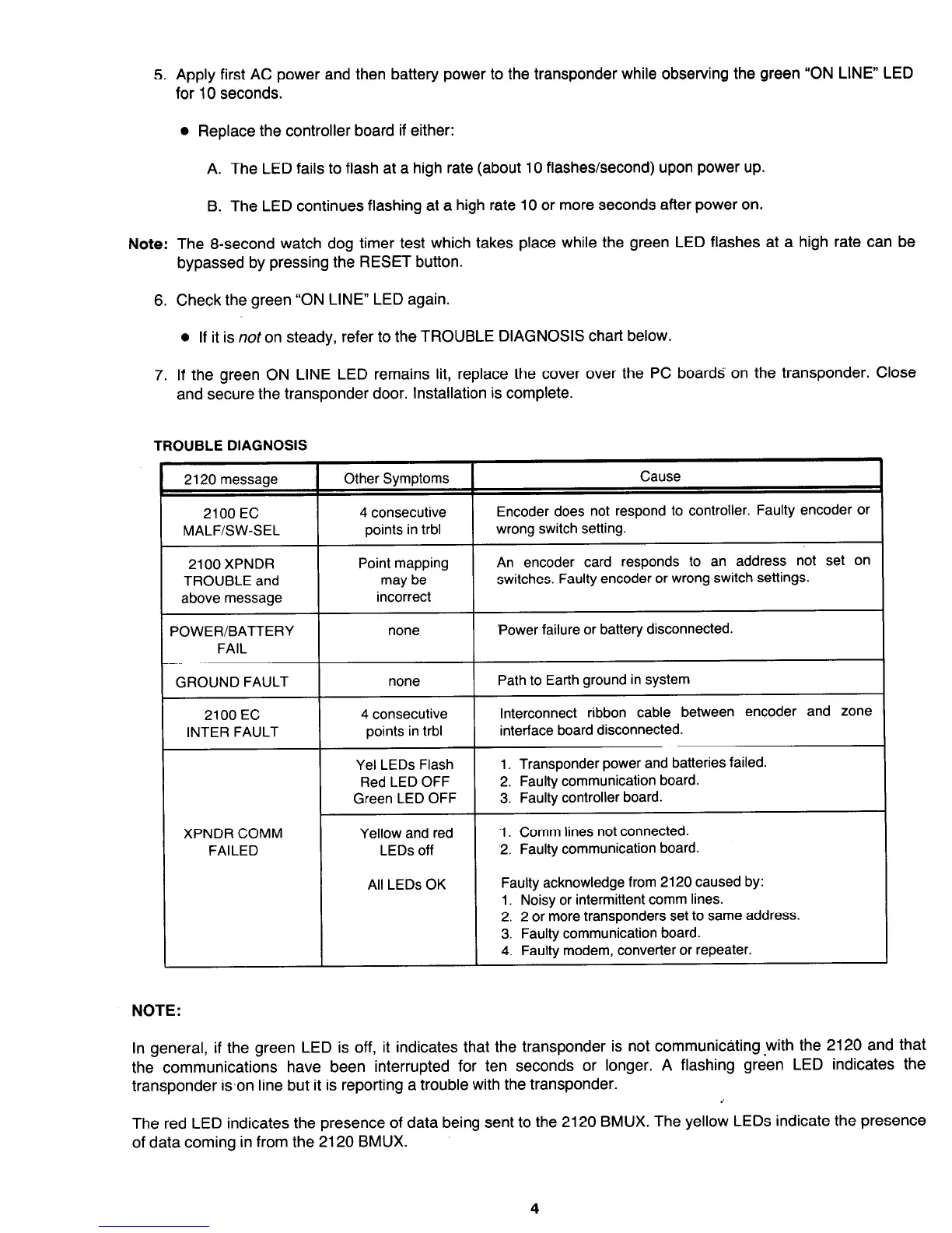
TROUBLE DIAGNOSIS
2120 message Other Symptoms
2100 EC 4 consecutive
MALFSW-SEL points in trbl
Cause
Encoder does not respond to controller. Faulty encoder or
wrong switch setting.
2100 XPNDR
TROUBLE and
I
Point mapping
An encoder card responds to an address not set on
may be
switches. Faulty encoder or wrong switch settings.
above message
POWER/BATTERY
FAIL
incorrect
none ‘Power failure or battery disconnected.
GROUND FAULT
none Path to Earth ground in system
2100 EC
INTER FAULT
XPNDR COMM
FAILED
4 consecutive
points in trbl
Yel LEDs Flash
Red LED OFF
Green LED OFF
Yellow and red
LEDs off
All LEDs OK
Interconnect ribbon cable between encoder and zone
interface board disconnected.
1. Transponder power and batteries failed.
2. Faulty communication board.
3. Faulty controller board.
‘1. Comm lines not connected.
‘2. Faulty communication board
Faulty acknowledge from 2120 caused by:
1. Noisy or intermittent comm lines.
2. 2 or more transponders set to same address.
3. Faulty communication board.
4. Faulty modem, converter or repeater.
NOTE:
In general, if the green LED is off, it indicates that the transponder is not communicating.with the 2120 and that
the
communications have been interrupted for ten seconds or longer. A flashing
green LED indicates the
transponder ison line but it is reporting a trouble with the transponder.
The red LED indicates the presence of data being sent to the 2120 BMUX. The yellow LEDs indicate the presence
of data coming in from the 2120 BMUX.
Technical Manuals Online! - http://www.tech-man.com
 Loading...
