8 Battery calculations
Each component of the panel has a specified alarm and standby current rating. To calculate the current draw for the system, add the
specified standby current for each module and device to obtain an alarm and a standby current rating for your system.
Note: Auxiliary power from the system’s AUX 24 V taps must also be included in the calculation unless that power is switched off during
battery standby. Notification Appliance load must be included in the alarm current total.
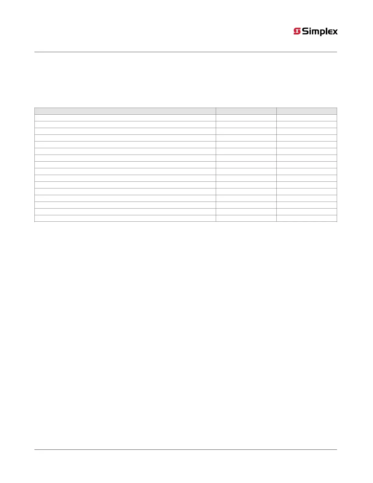
Table 9: Current for each module
Device / Module Standby Current (mA) Alarm Current (mA)
Photo / Heat Sensor with DIP SW 0.35 4
Photo Sensor with DIP SW 0.35 4
Heat Sensor with DIP SW 0.35 4
Triple Sensor with DIP SW 0.35 4
Mx Triple Sensor with Isolator and Address Switch 0.35 4
Mx Phot/Heat Sensor with Address Switch 0.35 4
Mx Photo Sensor with Address Switch 0.35 4
Mx Heat Sensor with Address Switch 0.35 4
Sounder Base 85db 10FT 0.01 24
Line Isolator Module 0.08 -
LCD Annunciator (w/ LCD ON) 65 72
2050 Main System Board draw 175 215
2250 Main System Board draw 185 225
Internal Gateway 125 125
External Gateway (Assembly with Cell modem) 145 145
City Circuit 30 60
Note: Device quantity selected at any point should ensure total current on MX LOOP is less than 945 mA.
Total standby current A (Note a) =____
Total alarm current B (Note b) =____
1. Identify Standby Time (C), in hours. C =____ (Typically 4, 12, 24 hr).
2. From previous calculations, locate total Standby Current (A) and total Alarm Current (B) in amperes. A=____ B = ____.
3. Identify Alarm Time (D) in minutes. D = ____ (Max 5 min).
4. Using the values in steps 1-3, perform an Initial Battery calculation as follows: (A x C) + (0.0167 x B x D), Initial Battery =____
Ah (Ah = ampere hours).
5. As per UL864 derating factor for battery to be chosen as Df = 20% or 0.2
6. Find the Derated Battery capacity using value in 4 and the derating factor: [Initial Battery/(1-0.2)], Derated Battery capacity
=____Ah
7. Select a battery size LARGER than the number from the Derated Battery calculation from the allowable battery sizes. Maximum
battery size that can be connected to the addressable panel is 25Ah.
Note:
• Consider all connected peripherals active during standby (any other Aux 24V load including).
• The maximum alarm current cannot exceed 6A (including NAC alarm current)
page 33 579-1404 Rev A
2050 and 2250 Foundation Series Fire Alarm Control Units Installation Guide