Suppression Release Peripheral Application and Installation Instructions
-385-02
Notes:
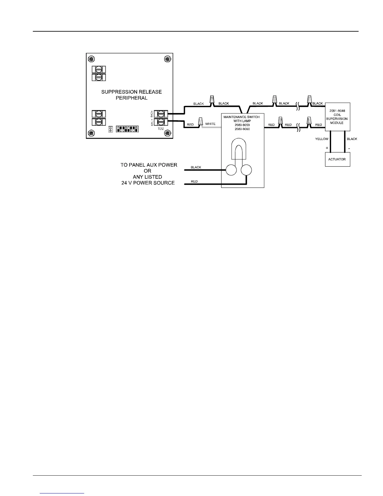
1. Connect the black wire to black and the red wire to red on the coil supervision module.
2. Refer to Table 3 for maximum RAC wiring distance based on 0.6 V, including supervision module. 0.6 V
Drop per Releasing Appliance Circuit (RAC) Output Interface description is on page 5 and Table 3. RAC
wiring is class B only.
3. When connecting two IDNet wires to one terminal, position one wire on each side of the terminal screw.
4. If a maintenance switch without a lamp (2080-9069, 2080-9070) is used, an auxiliary power source is not
needed.
Figure 5. Connections to Maintenance Disconnect Switch
Maintenance
Switch Wiring