Suppression Release Peripheral Application and Installation Instructions
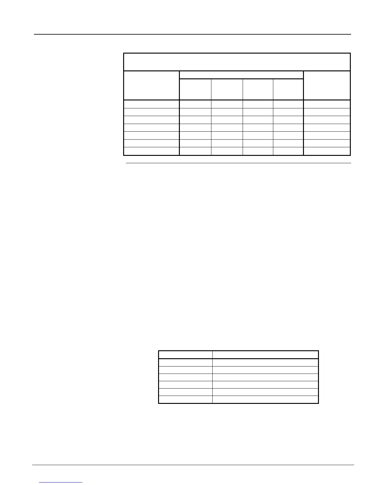
Table 3. SRP RAC Wiring Guidelines
MAXIMUM RAC WIRING DISTANCE
Based on a total Drop of 0.6 V
RAC OUTPUT
CURRENT
(Refer to
actuator rating)
The SRP RAC outputs are designated on the printed circuit board as RAC+ and RAC-.
The SRP RAC must connect to a 2081-9046-coil supervision module, which in turn
connects to a 12 V DC or 24 V DC actuator (see Figure 4). It can also connect to the
maintenance switches listed in Table 4. See Figure 5 for a connections diagram with a
maintenance switch.
All wiring must be 18 AWG (minimum) to 12 AWG (maximum).
Conductors must test free of all grounds.
All wiring is supervised and power limited unless otherwise noted.
Wiring between 2081-9046-coil supervision modules (Yell/Black) is not power limited.
Refer to the 2081-9046 Coil Supervision Module Wiring Instructions (574-437).
Connect 24 V DC actuator as shown, only one 24 V DC actuator per RAC +, - output.
Connect the 12 V DC actuator as shown. Two units must be connected through a
maximum of 20 feet in conduit.
For specific actuator wiring instructions, refer to the manufacturer’s recommendations.
For UL/ULC application, the RAC is a special application circuit, and must only be
used with the actuators listed in Table 5.
The RAC is compatible for use with any FM approved electric release deluge,
pre-action and refrigerated area sprinkler solenoid valve rated 22 watts or less. Refer
to the solenoid valve manufacturer’s product documentation for verification of agency
listings and power requirements.
Maximum alarm current is 2 A.
Earth Fault Detection on RAC is 2 kOhms or less.
Table 4. Maintenance and Abort Switches
Abort Switch Style C Flush
Abort Switch Style C Flush
Maint Switch w/Lamp Flush
Maint Switch w/Lamp Surface
Continued on next page