Installation
Related Documentation
The following is a list of additional documentation that may aid you in the
installation of the Graphical LCD Annunciator.
l
4 IOO+/412O/UT System Card Installation Instructions ................... 574-038
l
4020 Field
Wiring Diagram
.............................................................
841-842
l
4 100 Field Wiring Diagram
.............................................................
841-731
l
4 100 Field Wiring Diagram .............................................................
841-995
l
Graphical LCD Annunciator Field Wiring Diagram .......................
842-025
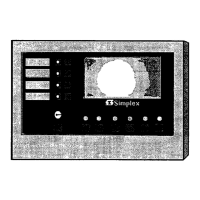
Unpacking the Annunciator
Unpack the annunciator using the following procedure.
1.
Lay the shipping container on a flat surface near the back box where the
installation is to take place.
2.
Carefully remove the plastic bands from the container and remove the container
cover.
3. Remove the packing material from the Graphical LCD Annunciator and remove
the unit from the shipping container.
4.
Lay the unit on a flat surface.
Install the back box using the following procedure.
1.
Connect a properly-grounded Static Ground Strap Assembly to your wrist.
2. Remove the four (4) screws holding the metal retainer and set them aside.
3. Remove the retainer from the assembly and set it aside.
4. Remove the four (4) screws holding the electronics assembly and set them aside.
5. Remove the electronics assembly from the back box and set it aside.
6. Remove the Static Ground Strap Assembly from your wrist.
7.
Place the back box on the wall over the junction box and mark the wall where
the top back box support screws will be placed.
8. Pull the wiring through the back box knockout.
9.
Thread the wiring through the strain relief and hang over the front edge of the
back box. (See Figure 2.)
Continued on next pag:
IO
 Loading...