13
B+ B- SHLD SHLD
NAC1
B+ B-
NAC2
B+ B-
NAC3
NAC2
NAC3
NAC1 NAC2 NAC3
A+ A- SHLD A+ A-
A+
A-SHLD
DIGITAL AUDIO DECODER MODULE
LED1 NAC1 LED2 NAC2
CLASS B EXPANDER
LED3 NAC3
NAC2
NAC3
SPEAKER
25/70.7 V
SPEAKER
25/70.7 V
RED
RED
RED
BLACK
BLACK
BLACK
SHIELD
SHIELD
SHIELD - WHEN REQUIRED
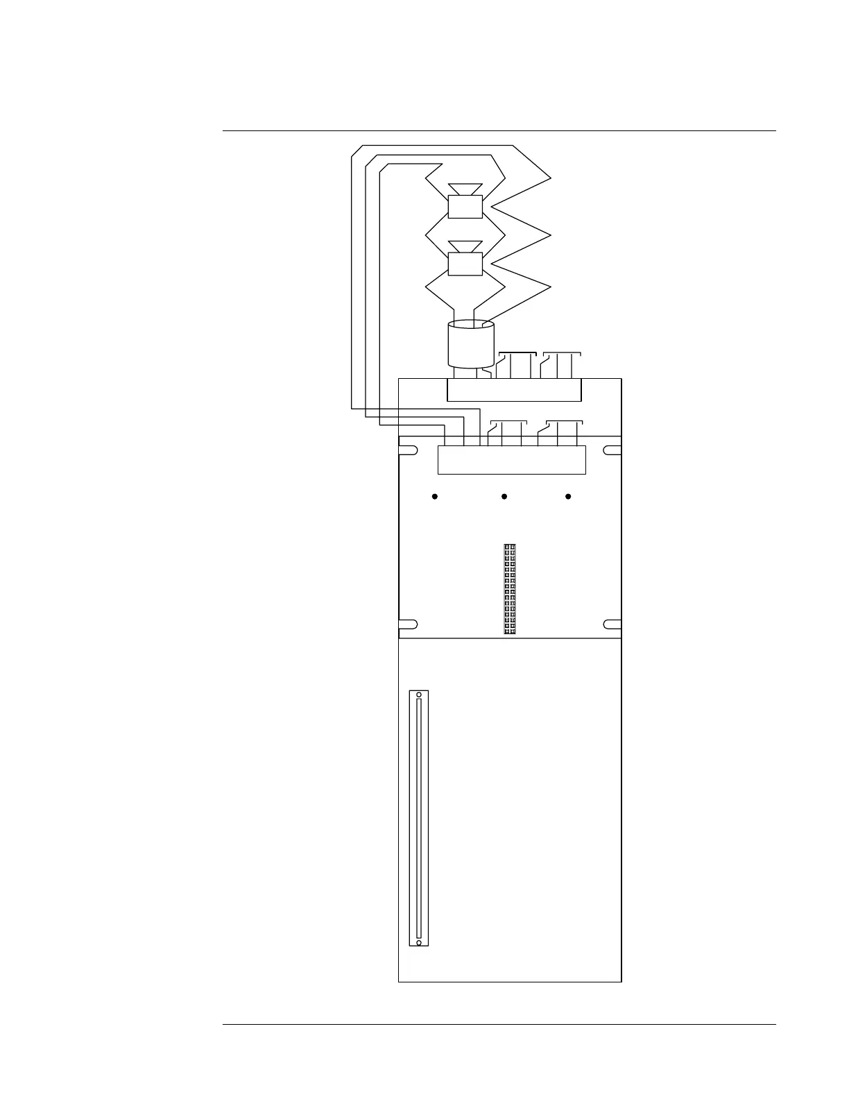
Figure 8. Class A Wiring
Continued on next page
Amplifier Field Wiring, Continued
Class A Wiring
• Leave the 10 K, ½ W resistors
(378-030; brown/black/orange) on
the “B+” to “B-” terminals of
unused circuits. Leave unused
“A+” and A-” terminals
unconnected.
• All wiring is between 18 AWG
(0.8231 mm
2
) and 12 AWG
(3.309 mm
2
).
• Field wiring is supervised and
power-limited.
• Total available Flex-50 power is
50 W (2A @ 25 VRMS, 0.707A @
70.7 VRMS).
• Total available Flex-35 power is
35 W (1.4A @ 25 VRMS, 0.5A @
70.7 VRMS).
• NACs and power stages can be
configured for any combination of
circuits as long as the total output
power does not exceed the
maximum specified rating.
Flex-35 Examples:
25 W to PS1 + 10 W to PS2
0 W to PS1 + 35 W to PS2*
Flex-50 Examples:
25 W to PS1 + 25 W to PS2
40 W to PS1 + 10 W to PS2
*This is an example of a self-
backing configuration. PS1 is not
loaded, but is saved for backup
should PS2 fail.
• Terminal designations “+” and “-”
are for the alarm state.
• Shields, when required, are
normally connected to 0 V as
shown. Alternate shield
termination using Earth ground is
provided on the amplifier chassis.