6
This section describes how to configure the amplifier’s baud rate and address using DIP switch
SW1. Configuration is the same for analog and digital amplifiers.
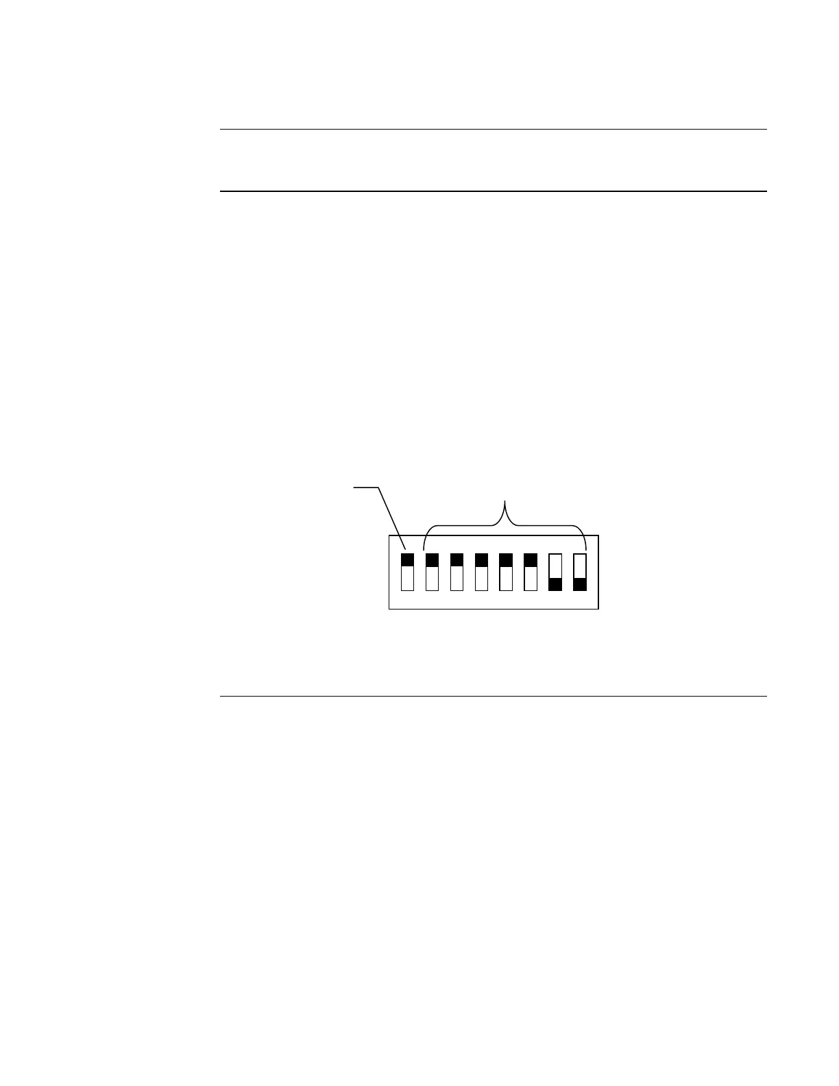
The device baud rate and address is set via DIP switch SW1, which is a bank of eight switches.
From left to right (see Figure 3, below) these switches are designated as SW1-1 through SW1-8.
The function of these switches is as follows:
• SW1-1. This switch sets the baud rate for the internal communications line running between
the card and the CPU. Set this switch to ON.
• SW1-2 through SW1-8. These switches set the card’s address within the FACP. Refer to
Table 1 for a complete list of the switch settings for all of the possible card addresses.
Notes:
• You must set these switches to the value assigned to the card by the Programmer.
• The SW1 setting applies to audio controller slaves, including audio input cards.
1
8
7
6
5
4
3
2
Figure 3. DIP Switch SW1
Continued on next page
Setting the Baud Rate and Address
Overview
Using DIP
Switch SW1
ON
OFF
DIP Switches SW1-2 through
SW1-8 set the Card Address.
Figure 3 shows an Address of 3.
4100 Comm. Baud Rate.
Switch (SW1-1)
Must Be Set to ON