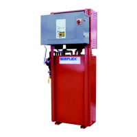
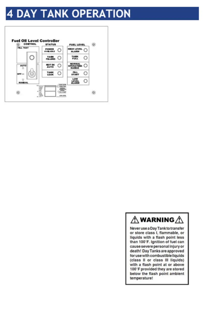
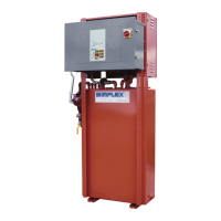
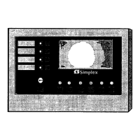
The control nameplate consists
of a durable, fuel oil resistant,
Lexan membrane which
contains the Day Tank control
pushbutton, switch and status
indicators. The control panel
contains a Fill Test pushbutton
(hold to test L.E.D. lamps), a
three position Day Tank Auto-
Off-Manual switch, and the
following L.E.D. lamps: Power
Available, Tank Filling, Tank
Leak, Not In Auto (blinking), High Level Alarm, Tank
Full, Normal Operating Range, Fill Start, and Low Level
Alarm. Day Tank operation is represented by the diagram
in the lower center of the nameplate.
The Day Tank control circuitry contains the following
serviceable components: motor starting contactor, and
control fuses. Control fuses are 2A, 250VAC, ABC type,
and the standard motor starting contactor is a double
pole, 24VDC coil, rated at 20A. The prime controller in
the Day Tank is the printed circuit board. The Day Tank
printed circuit board is powered by a fused internal
24VDC, 2A, power supply. The printed circuit board
utilizes 24VDC components to analyze the fuel level data
it receives from the four Day Tank fuel level sensors. The
four fuel level sensors
together with the sensor
mounting plate comprise
the fuel level sensor
assembly. When 120VAC,
single phase, 60Hz control
power is supplied to the
Day Tank control system
the Power Available L.E.D.
is illuminated. See Parts
Legend Drawing for
specific components used.