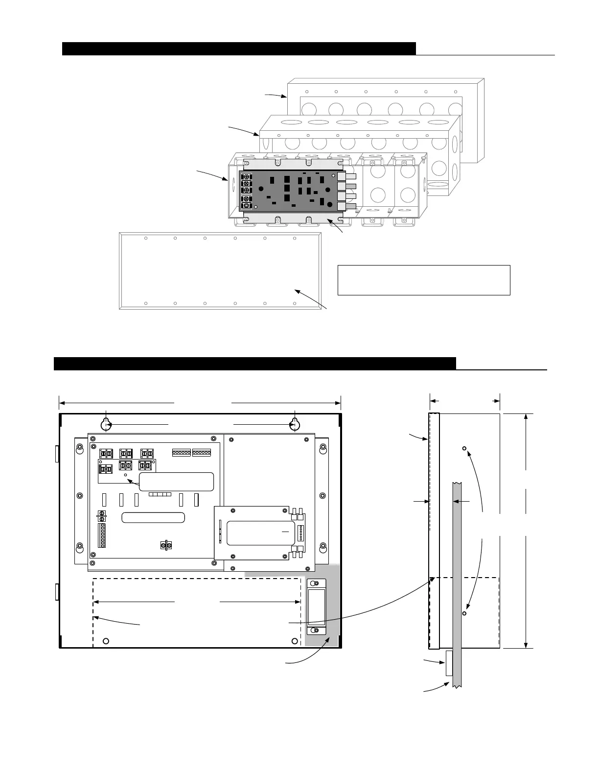
Cabinet depth
4-1/8" (105 mm)
16-1/4" (413 mm)
13-1/2"
(343 mm)
Wall surface reference for semi-flush mount
Non-power limited wiring area (AC input)
12" (305 mm)
Battery location, no conduit entry or wiring in
this area (12.7 Ah battery outline shown)
IDNet repeater or
Fiber optic receiver
Optional Class A
adapter module
10-29/32" (277 mm)
Knockouts for screw
or nail mounting holes
System Module
Optional Semi-Flush Trim Kit
1-3/16" wide (30 mm),
3/8" (9.5 mm) thick
Exposed cabinet
dimension for
semi-flush mount
1" (25.4 mm),
1-3/8" (35 mm) with
semi-flush trim
Door, 5/8"
(16 mm) thick
NOTE: Recommended conduit entrance varies with module selection. For models 4009-9401 and 4009-9402CA, refer to
Installation Instructions 574-762, specific option module installation instructions, and to Field Wiring Diagram 842-158
before locating conduit entrance. [NOTE: For model 4009-9501, refer to Installation Instructions 579-321 and Field
Wiring Diagram 842-244.]
6 S4009-0003-10 9/2015
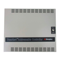
Surface mount box:
Simplex model 2975-9217
(ordered separately)
Flush mount masonry box:
use 6-gang box, RACO # 960, 2-1/2" deep
(64 mm), or RACO # 965, 3-1/2" (89 mm)
deep, or equal (supplied by others)
Six gang blank cover plate (Mulberry Metal
Products 97156 or equal), by others
Flush mount ganged boxes:
use 6-gang box, 1-1/2" (38 mm)
minimum depth; six, RACO # 400
or equal, (supplied by others)
IDNet fiber optic transmitter:
4090-9107, Shown, Class X (Style 7) output
4090-9105, Not shown, Class B (Style 4) output
INSTALLATION NOTE:
Fiber optic cable bend radius should be 2" (51 mm)
minimum, or per Manufacturer's specification.
TrueAlert Addressable Controller Mounting and Module Placement Reference
4090-9105/9107 IDNet Fiber Optic Transmitter Mounting Information
 Loading...