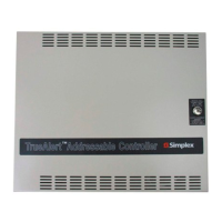
Input
Voltage
120 VAC Input (4009-9401/9402CA) 3 A @ 102-132 VAC, 60 Hz
240 VAC Input (4009-9501) 1.5 A, selectable for 220/240 VAC, +10% - 15% per selection, 50/60 Hz
Wired Control Input, requirements per circuit
3 mA @ 24 VDC; input voltage range = 16 to 33 VDC, filtered; control from conventional
reverse polarity NAC
Output Ratings
TrueAlert Channel Output Voltage (SLC) 19 to 31 VRMS, Special Application control
Compatible Special Application Appliances
Simplex TrueAlert and TrueAlert ES addressable notification appliances (with limitations);
contact your Simplex product representative for compatible appliances
Appliance Control
Characteristics
Category Details TrueAlert ES Appliance Control Limitation
Available Strobe Intensity 15, 30, 75, and 110 cd
Not compatible with TrueAlert ES intensities of
135 and 185 cd
Available Horn Control
Continuous, Temporal Code 3,
and March Time of 60 or 120 bpm
Not compatible with TrueAlert ES horn tones of
Temporal Code 4 or 20 bpm
Appliance Voltage
Minimum
17 VRMS
Not compatible with TrueAlert ES 23 VRMS appliance
voltage minimum
SLC Ratings
and Loading
TrueAlert Addressable
Controller or 4100ES TPS
Up to 63 total addressable appliances
Up to 75 unit loads (appliances are 1 unit load)
Up to 32 fixed candela (legacy) strobes can be synchronized per SLC
TrueAlert Addressable
Controllers
Up to 39 multi-candela strobes can be synchronized per SLC;
total current per controller = 8 A
4100ES TPS Up to 46 multi-candela strobes can be synchronized per SLC; total current per TPS = 9 A
Auxiliary Output 500 mA @ 24 VDC nominal (requires 734-035 wiring harness)
TrueAlert SLC Wiring UTP, unshielded twisted pair, 18 to 12 AWG
TrueAlert Strobe Wiring Distance Maximum wiring distance between TrueAlert strobes is limited to 30 Ω wire resistance
Wiring Connections Terminal blocks for 18 to 12 AWG
Optional Modules
IDNet Repeater
Module
(4009-9809)
Input Power 70 mA @ 24 VDC, system supplied
IDNet Input, One Address Maximum distance from IDNet source is 2500 ft (762 m)
IDNet Output
Specifications
Repeated IDNet output for up to 100 devices (total IDNet devices not to exceed 250 per
channel)
Refer to specific panels details for additional IDNet communications specifications
Fiber Optic
Receiver
Modules
Input Current
4009-9810 Class B, 65 mA @ 24 VDC, system supplied
4009-9811
Class X (Style 7), 80 mA @ 24 VDC, system supplied
(NOTE: Fiber optic input is Class X, repeated IDNet output is Class A)
IDNet Output Specifications Same as those for Repeater Module (see above)
Fiber Optic Transmission Distance = 3000 ft (914 m) maximum
General
Operating Temperature 32° to 120° F (0° to 49° C)
Operating Humidity Range 10% to 90% RH from 32° to 104° F (0° to 40° C)
Input Voltage 18.9-32 VDC from compatible listed fire alarm supply
Input Current
4090-9105 Class B, 30 mA @ 24 VDC
4090-9107 Class X (Style 7), 35 mA @ 24 VDC
Fiber Optic Connections
and Cable Requirements
(Type ST Connectors)
4090-9105 Class B input, two fiber cables required
4090-9107 Class X (Style 7) input, four fiber cables required
Module Size (with mounting bracket) 6-13/16” W x 3-3/4” H x 1-1/8” D (173 mm x 95 mm x 29 mm)
On-board Status Indicators
Green LED Flashing = transmit
Red LED Flashing = receive
4090-9107 Separate Red LED = Class X (Style 7) receive
Communications Simplex IDNet format
Fiber Optic Transmission Distance 3000 ft (914 m) maximum
Wiring Connections Terminal blocks for 18 to 12 AWG
Operating Humidity Up to 90% RH, non-condensing @ 100° F (38° C)
Operating Temperature 32° to 120° F (0° to 49° C)
7 S4009-0003-10 9/2015
TrueAlert Addressable Controller and 4100ES TPS Reference Specifications
NOTE: Refer to data sheet S4100-0065 for additional 4100ES TrueAlert Addressable Power Supply (TPS) specification details.
Fiber Optic Transmitter Specifications

 Loading...