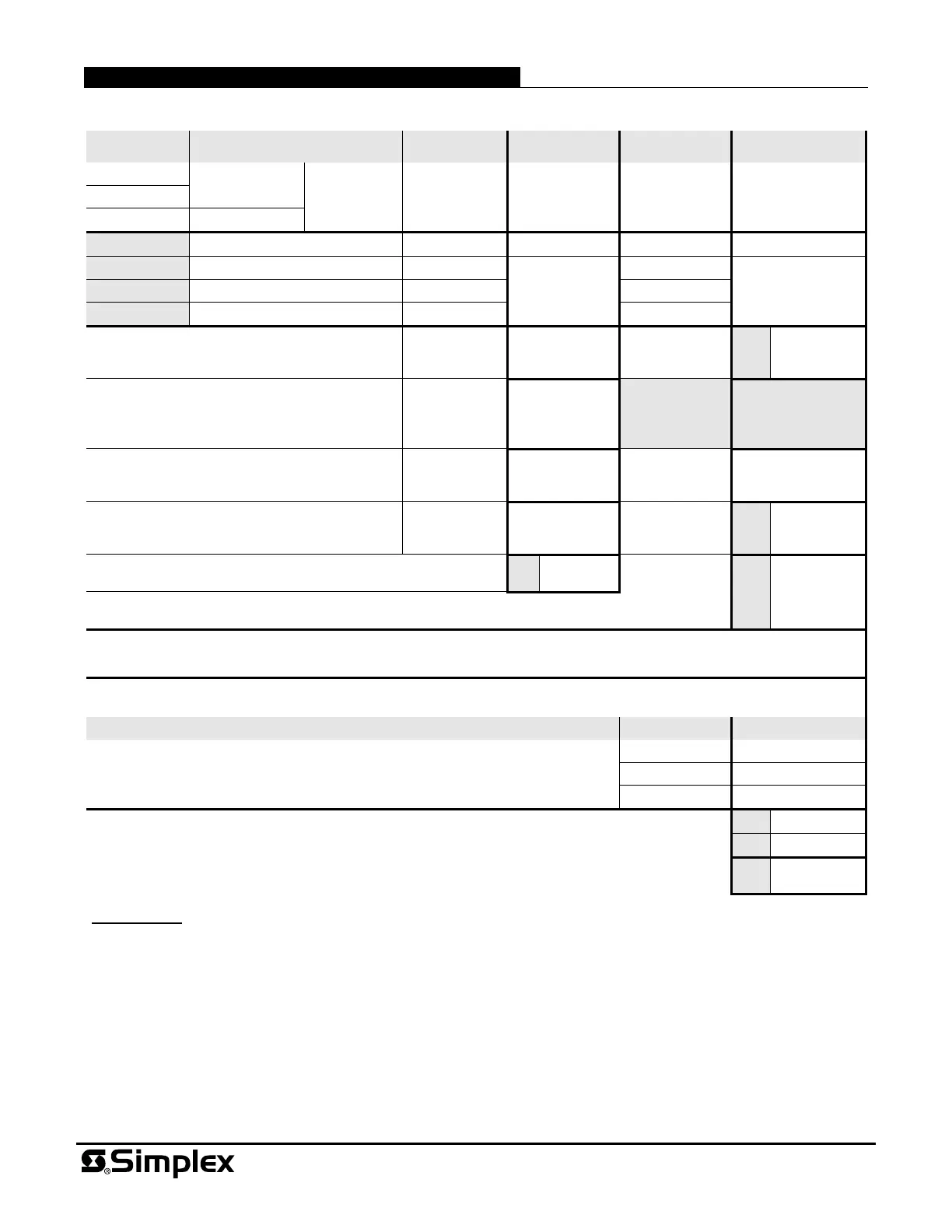
Panel Module Selection (shaded model numbers are optional modules)
Model Description
Supervisory
Current
Actual
Supervisory
Alarm Current Actual Alarm
4009-9401
120 VAC input
Basic Panel 88 mA 88 mA 195 mA 195 mA
4009-9402CA
4009-9501
240 VAC input
4009-9812
Class A Adapter 7 mA + 7 mA +
4009-9809*
IDNet Repeater 70 mA
+
70 mA
+
4009-9810*
†
Fiber Optic Receiver, Class B 65 mA 65 mA
4009-9811*
†
Fiber Optic Receiver, Class X 80 mA 80 mA
IDNet Devices, 0.7 mA each, maximum of 100
(see Procedure Note 5)
total devices
x 0.7 mA each
+
total devices
x 0.7 mA each
(A1)
+
TrueAlert Appliances/Devices, Supervisory
Current, 0.2 mA per unit load, add devices from
all 3 SLCs (see Procedure Note 7)
total loads
x 0.2 mA each
+
TrueAlert Isolators; each requires 1 address
and four (4) unit loads
total Isolators
x 10 mA
+
total Isolators x
10 mA
+
Auxiliary Power Output, calculate per total
device requirements (see Procedure Note 5)
500 mA
maximum
+
500 mA
maximum
(A2)
+
Total Supervisory Current =
(A)
(B1)
Total TrueAlert Addressable Controller Panel Alarm Current =
* Only one of these three modules can be chosen for a single TrueAlert Addressable Controller.
† NOTE: IDNet Fiber Optic Transmitter current is supplied from the host fire alarm control panel.
TrueAlert Channel Notification Appliance Current Loads
Channel Number NAC Alarm Current
TrueAlert Channel (SLC) 2.5 A maximum per channel (see Procedure Note 5)
Channel 1
Channel 2 +
Channel 3 +
Total TrueAlert Channel Loads Alarm Current =
(C)
Total TrueAlert Addressable Controller Panel Alarm Current (enter B1 from above) =
(B2) +
Total Alarm Current =
(D)
Procedure:
1. Calculate total panel supervisory current (A).
2. Calculate total panel alarm current (B1) [convert mA to A, example: 350 mA = 0.35 A]. Copy (B1) into block (B2).
3. Calculate total NAC loads alarm current from notification appliance ratings (C).
4. Add (C) + (B2) to determine total alarm current (D).
5. Total of IDNet Device Current (A1) + Auxiliary Power Output Current (A2) + SLC Loads Alarm Current (C) is 8 A
maximum.
6. Refer to Simplex battery selection document 900-012 for recommended battery size for specific standby requirements
(i.e., 24 hours supervisory, 5 minutes of alarm). Internal cabinet space is provided for batteries up to 12.7 Ah.
7. Most TrueAlert appliances/devices are one unit load, Isolators are 4 unit loads. Refer to Field Wiring Diagram 842-158.
Tyco Fire Protection Products • Westminster, MA • 01441-0001 • USA S4009-0003-10 9/2015
www.simplex-fire.com
© 2015 Tyco Fire Protection Products. All rights reserved. All specifications and other information shown were current as of document revision date and are subject to change without notice.
TYCO, SIMPLEX, and the product names listed in this material are marks and/or registered marks. Unauthorized use is strictly prohibited. NFPA 72 and National Fire Alarm and
Signaling Code are registered trademarks of the National Fire Protection Association (NFPA).
TrueAlert Addressable Controller Current Reference
 Loading...