2
579-1034
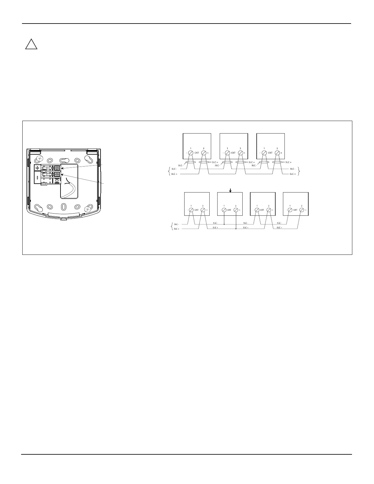
Wiring instructions
1. At the electrical box, connect the building wiring to the CKT + and CKT - terminals on the backplate.
2. To ensure proper continuity, use a torque wrench to tighten the terminal block screws to 12-15 inch-pounds.
3. Ensure that correct polarity is maintained for each unit.
4. Signaling Line Circuit (SLC) wiring must be twisted pair (TWP). CKT terminals accept two wires: 12-18 American Wire Gauge (AWG)
TWP .
Wiring notes
WARNING: Make sure that all power is disconnected before starting the installation.
IMPORTANT:
Do not bring the conduit through the rear of the electrical box. Strip the lead insulation to 7/16 inch
maximum.
Figure 2. Wiring instructions
• The maximum number of appliances on a circuit is 63. The maximum wire resistance between appliances is 26 ohms. See the field wiring diagrams
for the driving compatible fire alarm control panel for further instructions.
• Notification appliances are rated using an individual module label.
• Maintain the correct polarity on the terminal connections.
• Terminals 1 and 2 can each accommodate two wires, one wire going in and one wire going out to the next appliance.
• TrueAlert SLC wiring connections are supervised and power-limited.
• These appliances are rated to the operating voltage limits of 17-31 VDC. The appliance may fail to operate as intended, and cause permanent
damage to this equipment if it operates outside of these limits.
• Only operate the TrueAlert ES AO appliances using a compatible power supply.
• T-tapping is not permitted on Class A wiring.
Appliance backplate
From a compatible
SLC controller,
see notes
Terminal 2
CKT+
Terminal 1
CKT-
(T-tapping example)
A/O
A/O A/O
A/O
A/O A/O
A/O
From a compatible
SLC controller,
see notes
Class A wiring, see notes
Class B wiring, see notes
To the next appliance
or compatible SLC
controller, see notes