EasyManua.ls Logo

Simplex TrueAlert ES - User Manual

Simplex TrueAlert ES
4 pages
To Next Page IconTo Next Page
Loading...
579-1032 Rev F
TrueAlert ES Addressable UL Listed Multi-Candela Weatherproof Notification Appliances Installation
Instructions
*05791032F*
Cautions, Warnings, and Regulatory Information
IMPORTANT: When the notification appliance emits light or sound, it indicates the possibility of an emergency situation that requires immediate attention of all occupants.
SAFETY: Always install, maintain, and test notification appliances within their specifications. Failure to follow all safety precautions and instructions may result in loss of life and property due to non-functioning
notification appliances. Some notification appliances use high voltage. To avoid electrical hazards and avoid damage to appliances, make sure that the electrical power for the Notification Appliance Circuit is
disconnected at the control panel before installing, repairing, or internally adjusting any notification appliances. Even with electrical power removed, some notification appliances (such as visible strobes) store a high
voltage charge. The high voltage can cause injury resulting in death from electrical shock. DO NOT TOUCH EXPOSED CIRCUITRY.
LOCATION REFERENCE: Location and quantity of appliances required must conform to the applicable local standards and guidelines (the National Fire Alarm and Signaling Code (NFPA 72); ULC Standard CAN/
ULC-S524, Installation of Fire Alarm Systems; the appropriate model building codes, etc.) and specific requirements of the Local Authority Having Jurisdiction (AHJ). These notification appliances are not intended for
installation within hazardous locations as defined by the National Electrical Code (NEC) or NFPA.
UL listed TrueAlert ES Addressable weatherproof product identification reference
Type Colors Models Operation UL Compliance
100%
Fig 1: Wall Mount Visible Only (VO)
- Red
- White
Complete Devices:
49VO-WRFO
49VO-WRSO
49VO-WRFO-BA
49VO-WWFO-BA
49VO-WRSO-BA
Components:
49VO-APPLW-O
49VO-APPLW-O-BA
Backboxes:
4905-9828(red)
4905-9829(white)
49WPBB-AVVOWR (red)
49WPBB-AVVOWW (white)
Covers:
49VOC-WRFIRE-O
49VOC-WWFIRE-O
49VOC-WRALT-O
49VOC-WWALT-O
49VOC-WRFEU-O
49VOC-WWFEU-O
49VOC-WRBLNG-O
49VOC-WWBLNG-O
49VOC-WRS-O
49VOC-WWS-O
100%
Fig 2: Wall Mount
Audible Visible (A/V)
- Red
- White
Complete Devices:
49AV-WRFO
49AV-WRFO-BA
49AV-WWFO-BA
Components:
49AV-APPLW-O
49AV-APPLW-O-BA
Backboxes:
4905-9828 (red)
4905-9829 (white)
49WPBB-AVVOWR (red)
49WPBB-AVVOWW (white)
Covers:
49AVC-WRFIRE-O
49AVC-WWFIRE-O
49AVC-WRALT-O
49AVC-WWALT-O
49AVC-WRFEU-O
49AVC-WWFEU-O
49AVC-WRBLNG-O
49AVC-WWBLNG-O
49AVC-WRS-O
49AVC-WWS-O
These appliances are compatible
with 4100ES Fire Alarm Control
Panels (FACP), configured with
EPS controllers and optional 4009
IDNAC Repeater accessories. They
provide a VO or A/V warning of an
alarm condition when activated by
compatible Simplex FACPs.
The horn appliance complies with
the outdoor requirements of UL464.
The strobe appliance complies with
UL1638 outdoor use requirements
when set for the WP75 and WP185
candela output levels. When set for
the 15 and 75 candela output levels,
these appliances comply with UL1971
requirements for outdoor appliances
above the temperature range of 0
o
to
49
o
C.
Note: For information about device testing, see 4100ES Fire Alarm System Operator’s Manual (579-197).
Mounting instructions
1. Select the mounting location and install the weatherproof backbox using stainless steel screws suitable for the mounting surface. See Figure 3 for mounting and location information.
2. Attach the housing to the weatherproof backbox, ensuring there is even contact with the gasket around the periphery.
3. Use the mounting holes indicated in Figure 3, to secure the housing to the backbox. Use a torque wrench to tighten the screws to 5-7 inch-pounds, do not over-tighten.
4. Attach the cover to the weatherproof backbox using the screws provided. Use a torque wrench to tighten the screws to 5-7 inch-pounds, do not over-tighten.
NFPA 72 requires that the
entire lens is not less than
80 inches and not greater
96 inches above the
finished floor
Mount the unit
with the text
“This end up”
at the top
Housing
Cover
6-32, 7/16 inch screw
81 inches (2.06 m)
minimum to
mounting tabs
2 screw holes for
mounting the housing onto
the weatherproof backbox,
2 screws are supplied
IMPORTANT:
Do not use the back conduit entrance
for mounting weatherproof devices
3/4 inch conduit entrance
A watertight conduit fitting is
required for weatherproof devices
Weatherproof
backbox
Gasket, assembled onto
the weatherproof backbox
Fig 3: Mounting instructions

Other manuals for Simplex TrueAlert ES

Question and Answer IconNeed help?

Do you have a question about the Simplex TrueAlert ES and is the answer not in the manual?

Simplex TrueAlert ES Specifications

General IconGeneral
Power Supply24 VDC
Humidity Range10% to 93% non-condensing
ColorWhite or Red
Wiring2-wire
Visual Output15/30/75/110 candela options
FeaturesSelectable tone, synchronization
MountingWall or ceiling
Current DrawVaries by candela and tone
DimensionsVaries by model
WeightVaries by model

Summary

Cautions, Warnings, and Regulatory Information

General Safety Precautions

Essential safety guidelines for installation and maintenance to prevent electrical hazards and ensure proper operation.

Location and Regulatory Guidelines

Conformance to local standards, codes, and AHJ requirements for appliance placement and quantity.

Product Identification Reference

Wall Mount Visible Only (VO)

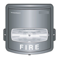
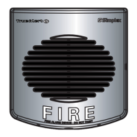
Identification of the VO model, including its visual-only notification function and mounting type.

Wall Mount Audible Visible (A;V)

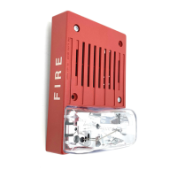
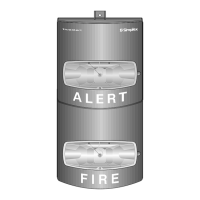
Identification of the A/V model, combining audible and visible notification features.

Mounting Instructions

Backbox Installation

Steps for selecting location and installing the weatherproof backbox using appropriate screws.

Housing Attachment

Securing the appliance housing to the backbox with proper contact and torque.

Cover Attachment

Fastening the cover to the backbox using specified screws and torque.

Wiring Instructions

General Wiring Precautions

Essential warnings and notes regarding power disconnection, wire gauge, polarity, and conduit use.

Signal Line Circuit (SLC) Wiring

Details on connecting CKT terminals, wire type, and maintaining continuity for SLC wiring.

Wiring Notes

Circuit Capacity and Resistance

Guidelines on maximum devices per circuit and wire resistance limits for proper operation.

Polarity and Module Labeling

Instructions on maintaining correct polarity and understanding appliance ratings.

Setting the Address

Addressable Device Configuration

How to assign a unique SLC address using the eight-position DIP switch for each device.

DIP Switch Operation

Steps for accessing and setting the DIP switches, including recording the final address.

Strobe Candela Setting

FACP Programming

Using the FACP setting for programming candela values, visible through the strobe lens.

Manual Candela Selection

Procedures for manually selecting candela settings (15, 75, WP75, WP185) using jumpers.

Device Configuration

Device Configuration Switch (SW3)

Explanation of the SW3 switch for configuring horn and strobe options directly on the device.

Configuration Options

Details on settings like Configuration Control, Audible Volume, CAN Horn Mode, and Legacy NAC mode.

Device Specifications

Environmental Specifications

Rated voltage, temperature, and humidity ranges for the notification appliances.

Candela (CD) Ratings

UL1638 candela ratings for various angles and conditions, detailing light output.

Sound Pressure Level (dBA)

Sound output levels for different settings (high/low volume, coded/steady) in reverberant and anechoic rooms.

Current Draw Specifications

Maximum RMS Operating Current

Table detailing current draw for different appliance types and candela settings under various conditions.

Light Output Percentage

Percentage of rated light output at various dispersion angles for 15cd and 75cd settings.

Related product manuals